5
Table of figures
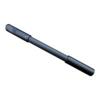
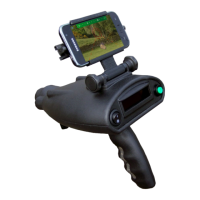
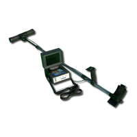
Figure 4.1: Overview of control elements .......................................................................................................... 18
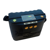
Figure 5.1: Charging the control unit before usage ........................................................................................... 20
Figure 6.1: Download and installation of the application .................................................................................. 22
Figure 6.2: Start activation ................................................................................................................................. 23
Figure 6.3: Scan QR code to activate the application ......................................................................................... 23
Figure 6.4: Enter serial number and activation code manually ......................................................................... 24
Figure 7.1: Starting the application and viewing the main menu ...................................................................... 26
Figure 7.2: Graphical depiction of a Bluetooth connection ................................................................................ 27
Figure 7.3: Activating the operating mode "Magnetometer" ............................................................................. 28
Figure 7.4: Activating operating mode "3D Ground Scan" ................................................................................. 30
Figure 7.5: Adjusting scan parameters individually ........................................................................................... 31
Figure 7.6: Establishing a Bluetooth connection in operating mode "3D Ground Scan" .................................. 32
Figure 7.7: "Zig-Zag" scan in operating mode "3D Ground Scan" ..................................................................... 33
Figure 7.8: Saving the current scan ................................................................................................................... 34
Figure 7.9: Adding field dimensions to the current scan ................................................................................... 34
Figure 7.10: Analysis controls in operating mode "3D Ground Scan" ............................................................... 35
Figure 7.11: Locating the folder with scan images ............................................................................................ 36
Figure 7.12: Browse scans in memory ............................................................................................................... 37
Figure 7.13: Settings .......................................................................................................................................... 38
Figure 8.1: Starting position of a scan area ....................................................................................................... 40
Figure 8.2: Scan modes to measure an area ..................................................................................................... 41
Figure 8.3: Effects of changing the number of impulses and their distance .................................................... 42
Figure 8.4: Comparison of low and high number of impulses .......................................................................... 42
Figure 8.5: Different walking speeds during scanning ...................................................................................... 43
OKM GmbH
www.okmdetectors.com