Note:
■ If a sensor is present in slot #5, then sensor in slot #2 is not monitored
■ The “combo” CO/H
2
S sensor can only be plugged in slot #4
■ The PID sensor can only be plugged in slot #5
Sensor slots and protection filters must be kept clean. Otherwise, gas
measurements could be jeopardized.
LCD Display
The instrument features a graphic LCD display with backlit (Figure 2, ref. 9). It
automatically illuminates when an alarm or a fault occurs. It can be rotated by 180°
using COM2100.
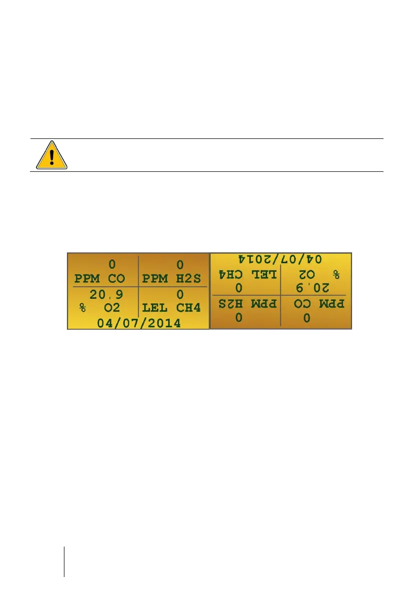
Figure 9: LCD display
The following information is displayed:
■ Up to 5 gas measurements along with gas names and units
■ Maintenance call for calibration
■ Date and time
■ Minimum and maximum values (peak) measured
■ STEL (short-term exposure limit) and TWA (time-weighted average) values
■ Remaining battery runtime (bargraph)
■ User’s and/or location’s identification
■ Maintenance menus
■ Alarm events (gas alarm, alarm transfer, sensor fault, battery fault, etc.)