Fault (no
communication
at all, sensor
fault, low
battery, etc.)
Tableau 2 : Controller Mode – Table of events
Start-up
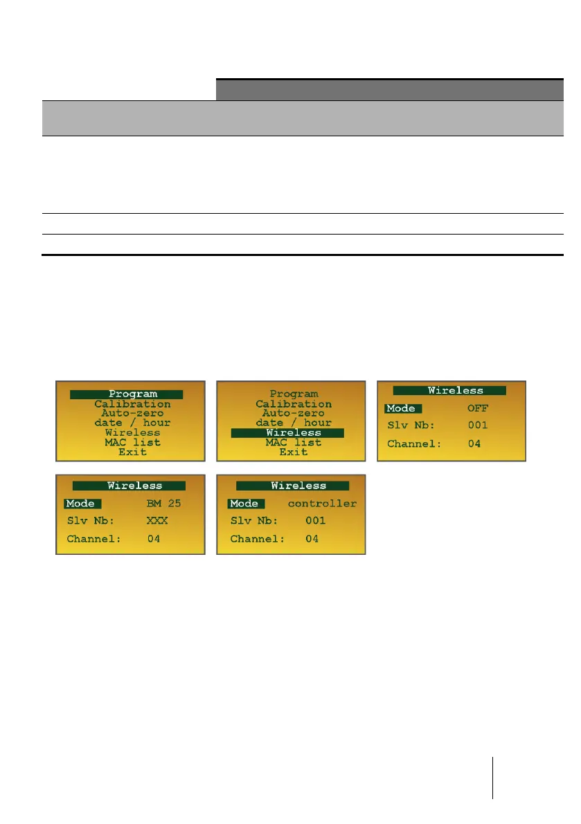
From the Maintenance menu (see Chapter 5), choose Wireless. Leave it to 'OFF' if you
do not want to activate the radio function. Select 'BM 25' or 'Controller' according to the
chosen operation mode (see above).
Figure 25 : Wireless mode screenshots
■ In BM 25 mode: only the network ID (Channel) must be set between 0 and 15.
Address number (Slv Number) is not editable and is set to 'XXX'. In this mode, it is
not necessary to assign an address as the network is automatically built in by using
the MAC
(*)
addresses of each device.
■ In Controller mode: set the BM 25W address Slv Nb between 1 and 30 max. and
the network ID Channel between 0 and 15.
(*) MAC (Media Access Control): unique identifier assigned to network interfaces. Each BM 25W
has its own unique MAC address.
WARNING