Controller Mode
In Controller mode, BM 25Ws send fault status, alarm status and gas measurements to
the controller. As soon as one BM 25W fires an alarm, the controller relays the gas
alarm information to all BM 25Ws on the same network that then turn in Alarm Transfer
mode.
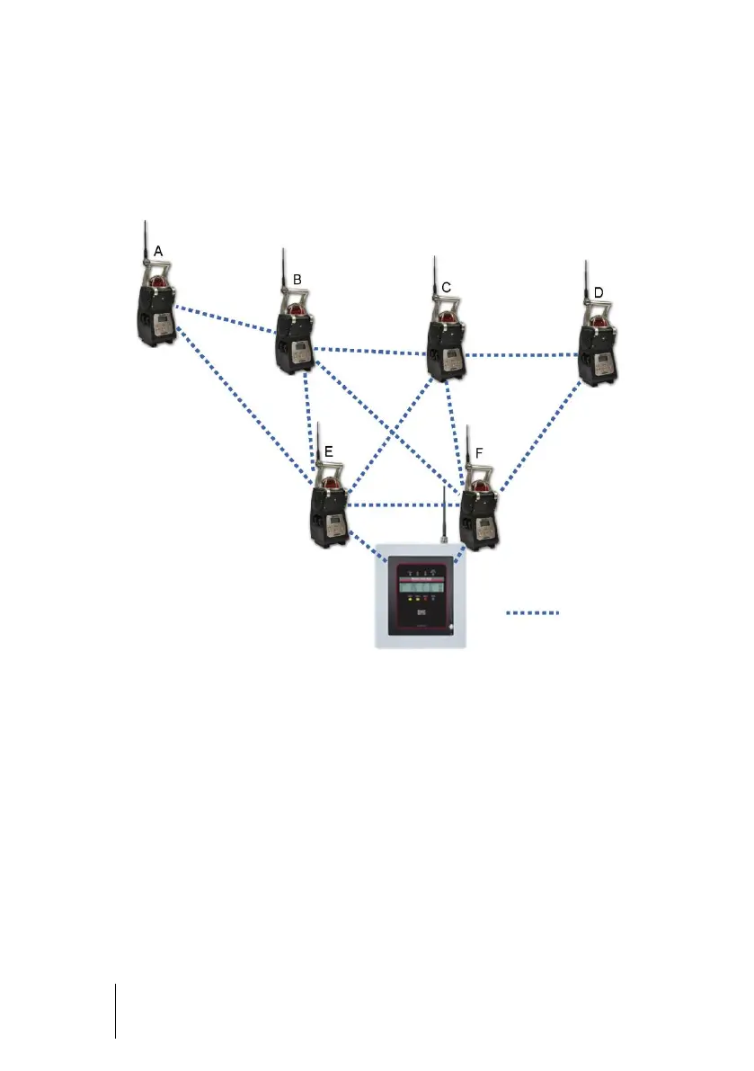
Figure 24 : In the example above, BM 25Ws E and F are the last links between the
controller and the rest of the network. If communication between BM 25W F and MX 40
fails, then BM 25W E continues to provide communication between the BM 25W network
and the controller. If BM 25W A goes into gas alarm or fault condition, then MX 40
receives information and passes the gas alarm on all others BM 25Ws
The alarm sequence differs depending on whether a BM 25W sends information (gas
alarm or fault) or receives information (alarm transfer). This allows for quick
identification of the BM 25W that is in alarm so that appropriate action can be taken.