Gas sensors
The sensors are located on the front of the monitor (Figure 2, ref. 10). They are smart,
pre-calibrated from factory and interchangeable. They are composed of a sensitive
element and electrical components, including an EEPROM memory in which the
sensor characteristics are stored (gas type, range, span value, instantaneous, STEL
and TWA alarm values, date of manufacture, serial number, date of last calibration,
span reserve, etc.). The span reserve is updated after each calibration and allows the
user to gage the optimal time for changing the sensor. Sensors must be positioned as
indicated in the table above.
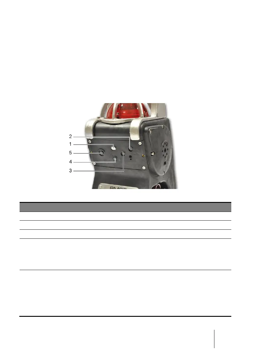
Figure 8: sensors configuration
Combustible gas sensor (0 to 100% LEL)
Mini sensors for toxic gases or the 1 year O
2
sensor
Mini sensors for toxic gases or the 1 year O
2
sensor
Medium sensors for:
■ O
2
(>2 year lifetime)
■ CO/H
2
S (combo medium sensor) and other toxic gases
■ CO
2
IR
Medium sensors for:
■ O
2
sensor (>2 year lifetime)
■ Toxic gases (medium sensors except CO/H
2
S sensor)
■ CO
2
IR
■ Infrared sensor for combustible gases
■ PID sensor for VOCs (Volatile Organic Compounds)