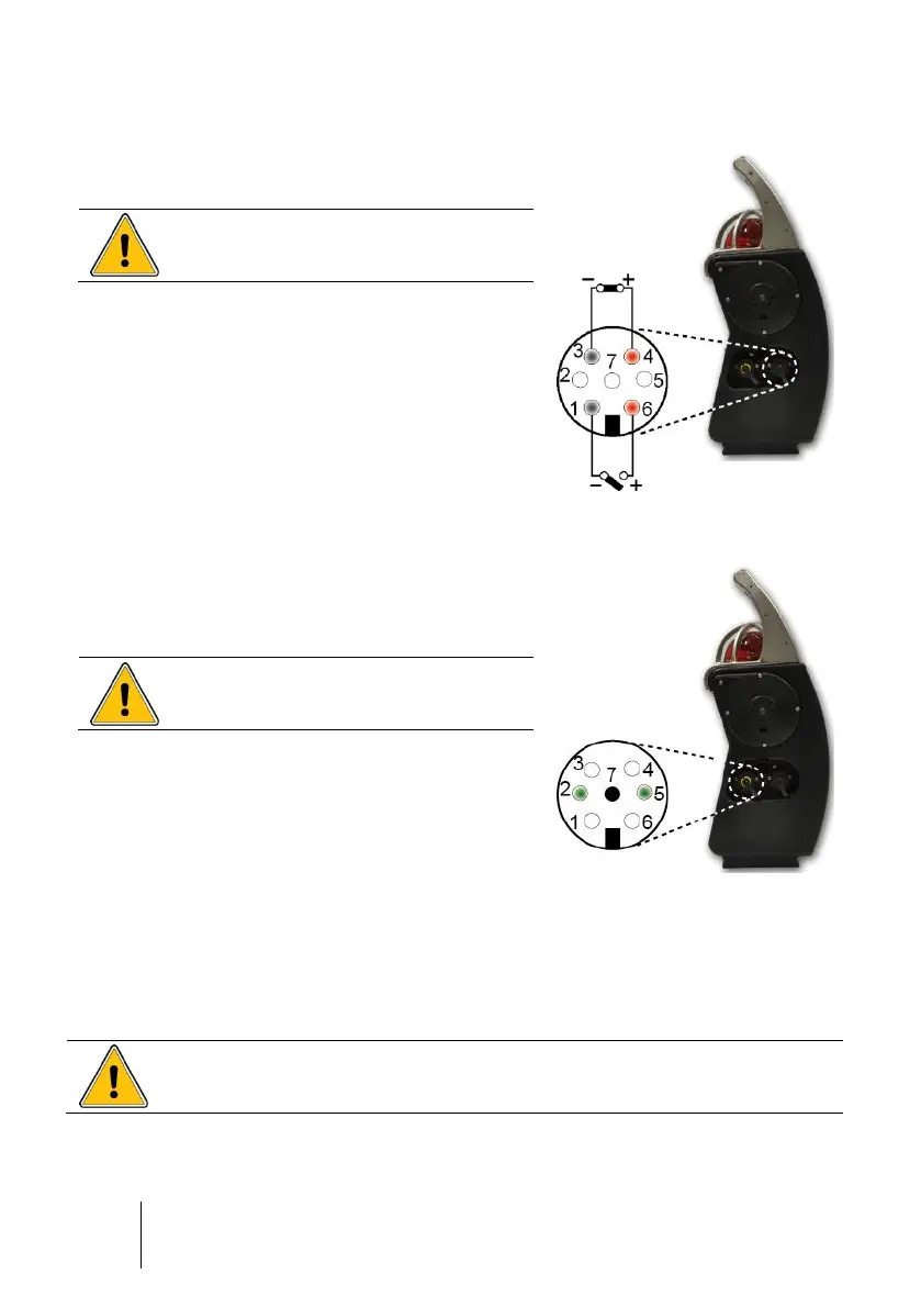
Relay Outputs (black ring)
■ Pins 1-6: alarm relay (NO) output
■ Pins 3-4: fault relay (NC) output
Unused connectors must be equipped
with their protective cap.
See details on pages 21 and 57.
Dry logic inputs (yellow ring)
■ Pin 2: logic input for alarm transfer
■ Pin 5: logic input for alarm acknowledgement
■ Pin 7: common ground
Unused connectors must be equipped
with their protective cap.
See details on pages 22 and 57.
Intrinsic safety parameters
■ Alarm relay output: dry relay contact,
Ui = 30 V, Ii = 150 mA, no L or C
condition
■ Power supply for trickle charging: Ui = 30 V,
Ii = 160 mA, no L or C condition
■ Dry logic input: Uo = 5 V, Io = 50 mA, Lo = 8
mH, Co = 7 µF
Figure 7: dry logic inputs
The person responsible for the gas monitor must create a Descriptive
System Document (for intrinsically safe circuits).