EasyManuals Logo

Oldham MX 32 Installation And Operating Manual

Oldham MX 32
48 pages
To Next Page IconTo Next Page
To Previous Page IconTo Previous Page
Page #16 background imageLoading...
Page #16 background image
MX 32
Instruction Manual
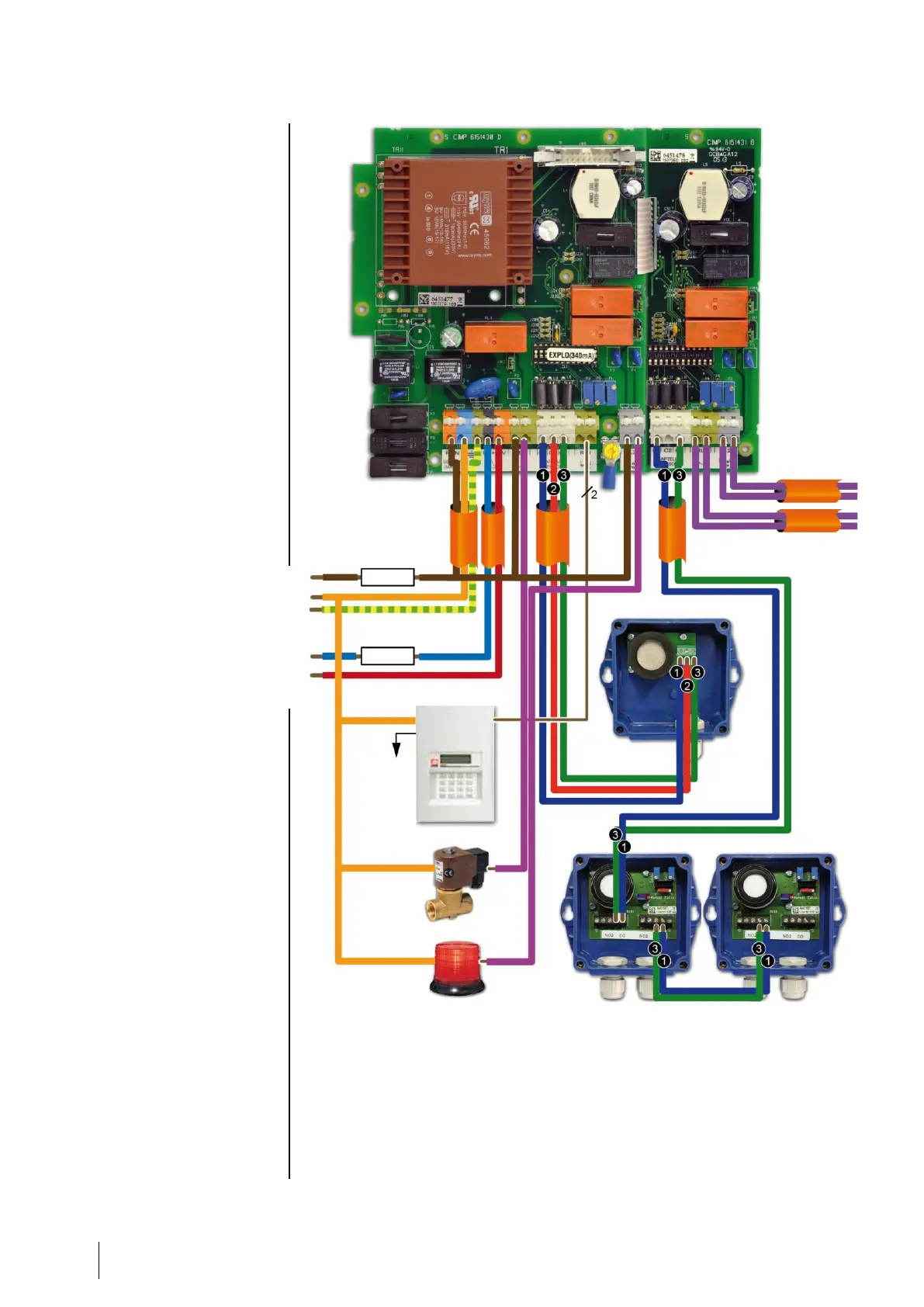
Figure 9: MX 32 controller with 1 explosive sensor on Channel 1 and 2 parking CO sensors
on Channel 2 (maximum of 5 loop-connected sensors).
Grounding sector
0V DC
+24 V DC
Telephonic
transmitter
To the
telephone line
Gas valve, closed
when power is cut off*
Shared fault indicator
Fuse or
circuit breaker
Fuse
Contact alarm
Channel 2.
Contact alarm
Channel 1.
The AL1 and AL2 relays can be programmed as
energized or de-energized (factory settings).
The fault relays are energized.
The contact relays are available on the NO or
NC terminals according to the position of the
switch next to each relay.
*Capacity to cut the power to relays 120 VA-
30W resistive; use a relay with external power
source if necessary.

Other manuals for Oldham MX 32

Questions and Answers:

Question and Answer IconNeed help?

Do you have a question about the Oldham MX 32 and is the answer not in the manual?

Oldham MX 32 Specifications

General IconGeneral
BrandOldham
ModelMX 32
CategoryController
LanguageEnglish

Related product manuals