Caution: when the measurement is above or equal to 100 % LEL,
the measurement controller records that the scale has been
exceeded; the channel switches to alarm and fault mode. The user is
responsible for manually rearming these settings, following the
safety regulations applicable at their site. Rearming can be
accomplished by restarting the controller or through a maintenance
operation.
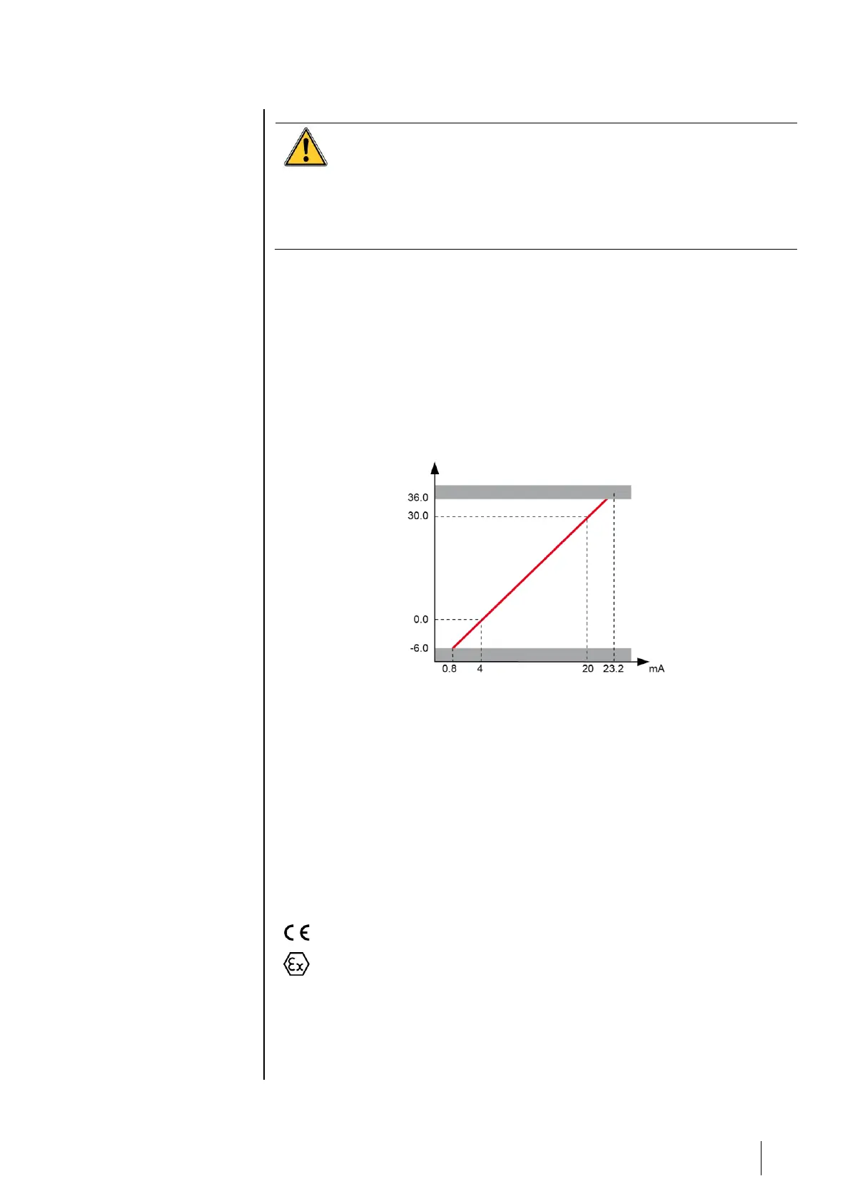
Configuration transfer curve 0 to 30.0 % oxygen
The following curve demonstrates the controller response in terms of values
measured and treatment of faults, as a function of the value of the input
current delivered by the detector. In the case that the user connects a non-
Oldham brand detector to the MX 32 controller, the user must ensure that the
transfer curve is compatible with the input characteristics for the controller, so
that the information delivered by the detector will be properly interpreted. In
addition, the controller must provide sufficient supply voltage, taking into
account voltage drops in the cables.
Figure 11: Configuration transfer curve 0 to 30 % oxygen
Power supply and resistance characteristics
■ Maximum current available between terminals 2 and 3: 250 mA
under 19 V.
■ Maximum voltage without load between terminals 2 and 3: 30 V.
■ Resistance (outside of the intrinsic safety barrier) between terminals
1 and 2: 47 ohm.
Markings:
OLDHAM Arras
0080
II (1) (2) G
INERIS 04ATEX0064