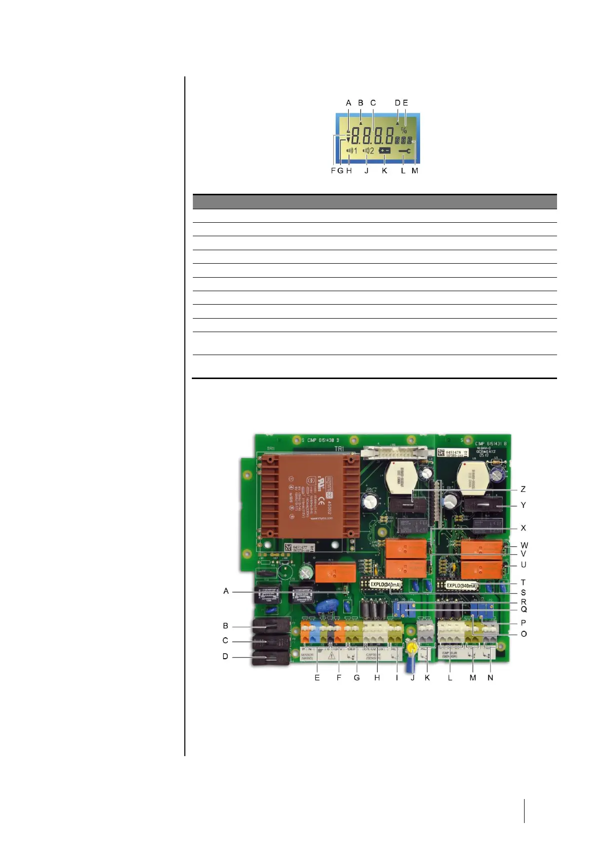
EasyManuals Logo

Oldham MX 32 Installation And Operating Manual

Oldham MX 32
48 pages
To Next Page IconTo Next Page
To Previous Page IconTo Previous Page
Page #9 background imageLoading...
Page #9 background image
2 General Introduction
5
LCD Information
Figure 3: LCD Information.
Ref.
Function
See page
A.
Indicator for alarm threshold rising.
13
B.
Indicator that Channel 1 is selected. See Figure 2, ref. D.
14
C.
Digital indicator (measurement value, alarm threshold value, etc.)
13
D.
Indicator that Channel 2 is selected. See Figure 2, ref. D.
14
E.
Percent symbol.
18
F.
Negative sign.
G.
Indicator for alarm threshold falling.
18
H.
Symbol indicating level 1 alarm threshold (AL1) activated.
18
J
Symbol indicating level 2 alarm threshold (AL2) activated.
18
K.
Time delay after calibration (blocking the relays): the yellow LED blinks
and the icon is displayed.
18
L.
A Maintenance key icon is displayed while the programming and
calibration menu is being used.
18
View: Internal
Figure 4: Internal view.

Other manuals for Oldham MX 32

Questions and Answers:

Question and Answer IconNeed help?

Do you have a question about the Oldham MX 32 and is the answer not in the manual?

Oldham MX 32 Specifications

General IconGeneral
BrandOldham
ModelMX 32
CategoryController
LanguageEnglish

Related product manuals