l
e prescrizioni della norma IEC 364) mediante
dispositivo a corrente differenziale (normal-
mente con corrente nominale d’intervento pari
a 0,03 A).
3. A
ssicurare all’origine del cavo di alimentazio-
ne una protezione contro i contatti diretti pari
ad almeno IP2X o IPXXB.
4. Installare all’origine del cavo di alimentazione
un dispositivo che protegga lo stesso dalle
sovracorrenti (cortocircuito), vedere indicazioni
nello schema elettrico.
5. Utilizzare conduttori che portino la max cor-
rente richiesta alla max temperatura ambiente
di funzionamento, secondo il tipo di installa-
zione scelto (IEC 364-5-523 ) (vedere indica-
zioni nello schema elettrico).
Tabella dati elettrici per il dimensionamento
della linea di alimentazione
I
ndicazioni nello schema elettrico:
a) massima taglia ammessa del fusibile tipo gG .
In generale, i fusibili possono essere sostituiti
da un interruttore automatico regolato sulla
max corrente assorbita dalla macchina
(contattare il costruttore se necessario)
b) sezione e tipo di cavo di alimentazione:
• installazione:
conduttori isolati, cavo multipolare in condotto,
in aria o sopra muratura (tipo C secondo
IEC 364- 5-523 1983) o senza nessun altro
cavo a contatto.
• tipo di cavo:
c
onduttori di rame, isolamento in PVC da 70 °C
(
se non specicato ) o isolamento in EPR da 90 °C.
Il cablaggio del cavo di alimentazione elettrica è a
cura del cliente.
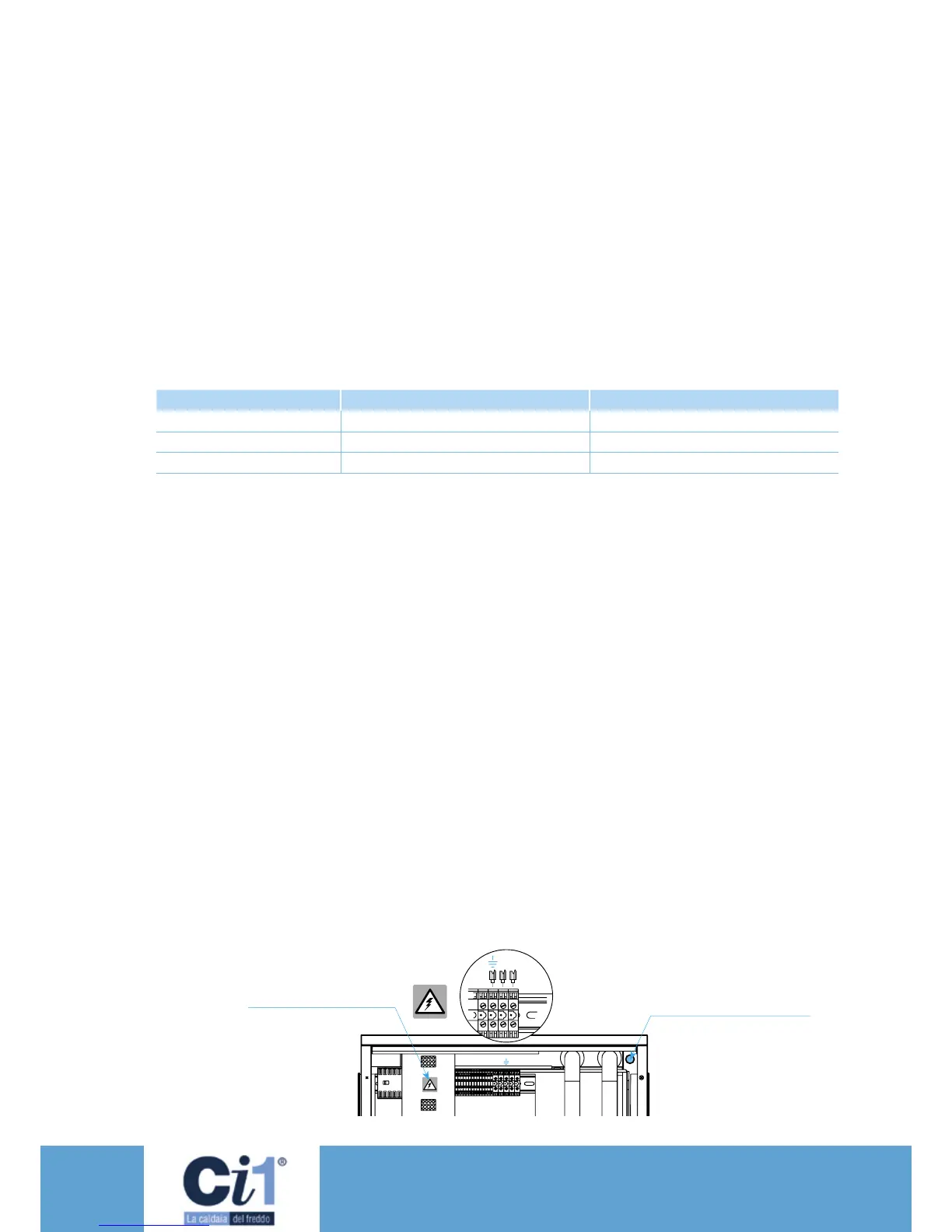
Far passare il cavo di alimentazione dalla parte
posteriore della macchina insieme ai collegamenti
idraulici (vedi gura), tirandolo no a raggiungere
il quadro elettrico.
Cablare il cavo sulla morsettiera come indicato in
gura e nello schema elettrico.
Modello Model
I max (A) P max (kW)
Ci5
Ci7
Ci10
12
16
25
2,5
3
4,5
Rischi di shock elettrico
Electric shock hazards
contacts according to the prescriptions of IEC
364 Standard) by means of a differential
current switch (normally with operation rated
current of 0.03 A).
3.
At the beginning of the power supply cable,
provide a protection against direct contacts, with
a protection degree of at least IP2X or IPXXB.
4. At the beginning of the power supply cable,
install a device protecting against overcurrents
(short circuit), see indications in the electrical
diagram.
5. Use conductors able to bear the power load
required at the max working ambient tempera-
ture, according to the chosen type of
installation (IEC 364-5-523) (see indications in
the electrical diagram).
Table of electrical data for the dimensioning
of the power supply line
Indications in the electrical diagram.:
a) Max. size allowed for fuse of type gG.
In general, the fuses can be replaced by an
automatic switch set of the max current
absorbed by the machine (contact the
producer, if necessary).
b) power supply cable, section and type:
• installation:
insulated conductors, multipole cable in duct,
air or above masonry (C type according to
IEC 364-5-523 1983 ) or without any other
contacting cable.
• type of cable:
copper conductors, PVC insulation by 70°C
(if not specied) or EPR insulation by 90°C.
The wiring of the power supply cable is the cu-
stomer’s responsibility.
Route the power supply cable from the rear part
of the machine together with the hydraulic con-
nections (see gure), pulling it up until it reaches
the electric panel.
Connect the cable to the terminal board, as
shown in the gure and in the electrical diagram.
Foro per passaggio cavo di
alimentazione
Hole for the passage of the
power supply cable