31
4.2 COLLEGAMENTI IDRAULICI
Nella parte posteriore della macchina sono pre-
senti gli attacchi acqua lettati con il
diametro dei
tubi esposto nel paragrafo 4.1.4
1) Collegare la macchina alle tubazioni del
l’acqua rispettando la direzione dell’acqua
come indicato nelle gure e dalle frecce
presenti sulle tubazioni di collegamento.
2) Prevedere due rubinetti (uno in ingresso e uno
in uscita) per escludere la macchina in caso
di manutenzione senza dover svuotare il
circuito dell’acqua dell’utilizzatore.
3) Riempire l’impianto di acqua utilizzando:
• Un sistema di caricamento remot
o o quello
presente nella macchina.
• In questo caso è necessario satare manual-
mente l’aria del serbatoio agendo sulla
valvola manuale (*).
• Se ci sono frequenti inltrazioni di aria nel
circuito dell’acqua è consigliabile installare una
valvola di sato automatico.
(*) Accertarsi (controllando sul manometro la
pressione del serbatoio con pompa ferma) che la
pressione nel circuito dell’acqua sia compreso tra
0,5 ed 1 bar a refrigeratore spento.
Attenzione!
Per il corretto funzionamento è necessario instal-
lare un ltro/acqua da collegare alla tubazione di
ingresso (per esempio un ltro a “Y”).
La mancata osservanza di questa prescrizione
può essere la causa di danni irreparabili all’eva-
poratore.
L’impianto idraulico deve essere dimensionato
in modo tale che nella macchina non afuisca
acqua con valori di pressione superiori a quelli
esposti nella tabella della pagina seguente.
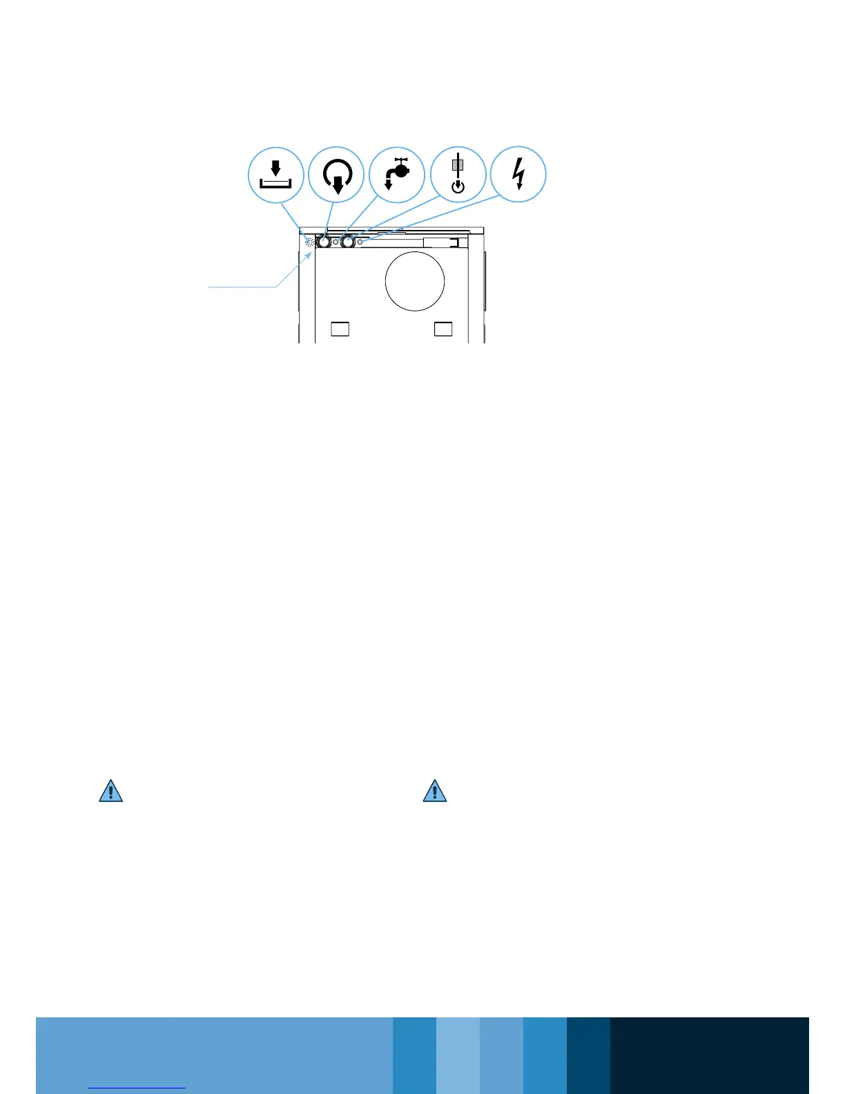
Vista posteriore dell’unità
Machine rear view
3
4.2 HYDRAULIC CONNECTIONS
Threaded water ttings are located in the rear
part of the machine. The diameter of the pipes is
indicated in paragraph 1.4.4
1) Connect the machine to the water pipes,
respecting the direction of the water ow as
shown in the gures and by the arrows on
the connection pipes.
2) Install two taps (one on the inlet and one
on the outlet) to isolate the machine’s water
circuit in case of maintenance without having
to empty the water circuit of the user.
3) Fill the system with water using:
• A remote loading system or that present in
the machine.
• In this case, the air in the tank must be
bled out every year, using the manual
valve (*).
• Should air inltrations in the water circuit
be frequent, we recommend installing an
automatic bleed valve.
(*) Check the tank’s pressure gauge when
the pump is not operating and make sure
the pressure in the water circuit is between
0.5 and 1 bar,
with chiller off.
Attention!
For the machine to operate properly, it is
necessary to install a water lter on the inlet
pipe (for instance a “y” lter).
Failure to observe this prescription can cause
irreparable damages to the evaporator.
The hydraulic plant must be dimensioned so
as to prevent water with excessive pressure
from entering the machine (for proper water
pressure values see table in the following page).
Collegamenti
essibili
Flexible
attachments