35
4.5 COLLEGAMENTI ELETTRICI
Attenzione!
Prima di eseguire l’installazione o di operare su
queste macchine, assicurarsi che tutto il per-
sonale abbia letto e compreso il capitolo sulla
Sicurezza di questo manuale.
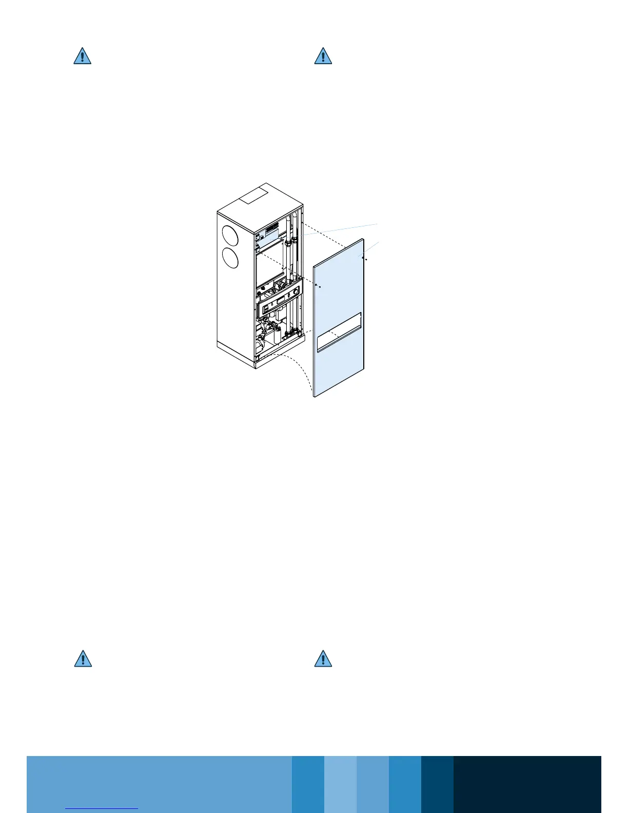
• Per accedere ai componenti del quadro elettri-
co (A), togliere il pannello anteriore (B) svitan-
do le viti di ssaggio.
A questo punto è possibile avere accesso ai
componenti.
• Il collegamento dell’unità alla rete di alimenta-
zione elettrica deve essere realizzato in con-
formità alle leggi ed alle prescrizioni vigenti
nel luogo di installazione.
• Il voltaggio e la frequenza devono essere
conformi a quanto riportato sulla targa della
macchina.
• La tensione di alimentazione non deve, neppu-
re per brevi periodi, essere fuori dalle tolleran-
ze riportate sullo schema elettrico.
Salvo diversa indicazione, la tolleranza sulla
frequenza è pari a +/- 1% del valore nominale
(+/-2% per brevi periodi).
• Nell’ alimentazione monofase, la tensione
deve essere fornita fra fase e neutro e
quest’ultimo conduttore deve essere collegato
a terra nella propria cabina di trasformazione
(impianto TN secondo IEC 364) o da parte
dell’ente erogatore (impianto TT secondo IEC
364). Il conduttore di fase e quello di neutro
non devono essere scambiati fra loro.
Attenzione!
1. Collegare la macchina (terminale PE nel
quadro elettrico) all’impianto di terra dell’edicio
2. Garantire l’interruzione automatica dell’alimen-
tazione in caso di guasto dell’isolamento
(protezione contro i contatti indiretti secondo
B
A
4.5 ELECTRICAL CONNECTIONS
Attention!
Before installing or operating these machines,
make sure all the personnel has read and fully
understood the chapter on Safety included in this
manual.
• To access the components of the electric
panel (A), remove the front panel (B) by un
screwing the xing screws. Only now it is
possible to access the components.
• The connection of the unit to the electric mains
must be performed in compliance with
the laws and prescriptions in force in the
installation place.
• The voltage and the frequency must comply
with the requirements stated in the machine’s
data plate.
• The feeding voltage must never exceed the
tolerances indicated in the electrical diagram.
Except if differently stated, the tolerance on
the frequency is equal to +/-1% of the rated
value (+/-2% for short periods).
• With single phase power supply, the voltage
must supplied between phase and neutral,
and this latter conductor must be earthed in its
own transformer cabin (TN system complying
with IEC 364) or by the electricity supply
company (TT system complying with IEC 364).
The phase conductor and the neutral con-
ductor must not be swapped.
Attention!
1. Connect the machine (terminal PE in the
electrical panel) to the building’s earth system.
2. The automatic interruption of the power supply
must be guaranteed in case of breakdown
of the insulation (protection against indirect