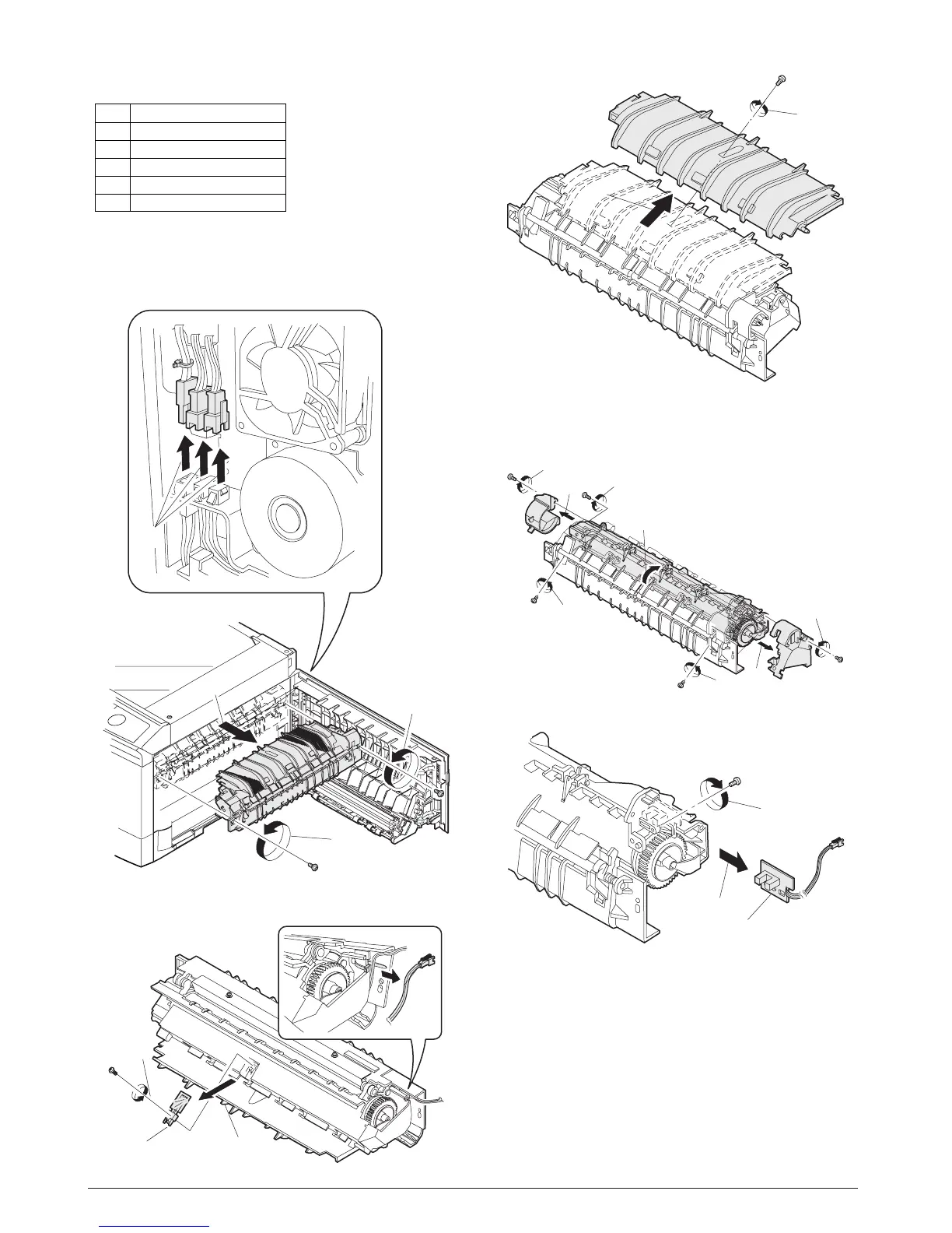
4. Fusing section
A. List
B. Disassembly procedure
1) Remove the connectors (3 pcs.) of the rear cabinet.
2) Open the side cover, remove two screws, and remove the fus-
ing unit.
3) Cut the binding band, remove the screw, and remove the ther-
mistor.
4) Remove the screw and remove the U-turn guide.
Pressure roller section disassembly
5) Remove the three screws, remove the fusing cover lower on
the right side, and open the heat roller section.
6) Remove the screw and remove the PPD2 sensor.
No. Part name Ref.
1 Thermistor
2 PPD2 sensor
3 Heater lamp
4 Pressure roller
5 Heat roller
1)
2)
3)
2)
1)
2)
3)
Thermistor
1)
2)
1)
5)
5)
6)
6)
4)
3)
2)
1)
2)
PPD2 sensor
Y109500-5 Service Manual 8-5

 Loading...