Do you have a question about the Olsberg MultiDrive 3 and is the answer not in the manual?
The control system fulfills stringent safety requirements in terms of reliability and operational safety.
Describes the radio remote control system, its components, and FCC compliance.
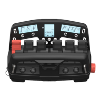
Details information shown on the side and centre displays for operator feedback.
Explains the decoder's role in translating radio traffic and the importance of pairing for safety.
Describes the function of LEDs L1, L2, L3 and various blink modes for different operating cases.
Describes the hand controller's six levers, configurable buttons, and operation.
Explains how levers and displays show function symbols and operation direction.
Details how the micro-button adjusts lever sensitivity for precise crane operation.
Instructions on installing the battery and activating the hand controller.
Steps to turn on the crane's unit, establish radio connection, and decoder activation.
Details when the radio link is established, signal strength display, and handling connection disruptions.
Describes the three main menus (CRANE, EXTRA, ON-OFF) and how to select sub-menus.
Highlights the system's ability to switch between operations and automatic restart.
Explains how side displays show symbols representing functions controlled by levers in CRANE mode.
Illustrates CRANE 3, CRANE 2, and CRANE 1 sub-menus with corresponding lever functions.
Covers additional hydraulic functions and how symbols/descriptions are configured.
Shows sub-menus for Cranes with 1 or 2 stabiliser valves, detailing functions like leg/stab extension.
Describes ON-OFF functions like start, stop, throttle, and their control via levers.
Illustrates ON-OFF 2 and ON-OFF 1 menus with functions like lights and LSS.
Explains the centre display as an information centre for non-crane operation details.
Details symbols for Fault, Micro, Service, Personnel basket/VSL+, Signal strength, and Main menu indicators.
Explains indicators for ADC, JDC, HDC/LSS, Manual extension, and Battery capacity.
Explains how selected functions are enlarged and how fault indications appear.
Details how to display error codes using the info button and how they scroll.
Explains OLP, defining Crane-OLP, Outrigger-OLP, and VSL-OLP based on load limits.
Illustrates how Crane-OLP, Outrigger-OLP, and VSL-OLP are shown on the displays.
Describes how OLP blocks functions, shows a cross symbol, and how to release with the stop button.
Details how pressure sensors show warning levels (50-100%) and blocking at 100%.
Procedure to lock/unlock the controller and effects of low ambient temperatures on displays.
Explains fault indication (spanner symbol) when safety system communication fails.
Steps for pairing a new controller/decoder, including connection and LED status.
Explains operating the controller via cable for short-term use, pairing, or permanent installation.
Procedure to activate manual extension for capacity calculation and disengage the function.
Lists part numbers, Hiab numbers, descriptions, and notes for controller components.
Lists part numbers, Hiab numbers, descriptions, and notes for decoder and radio components.