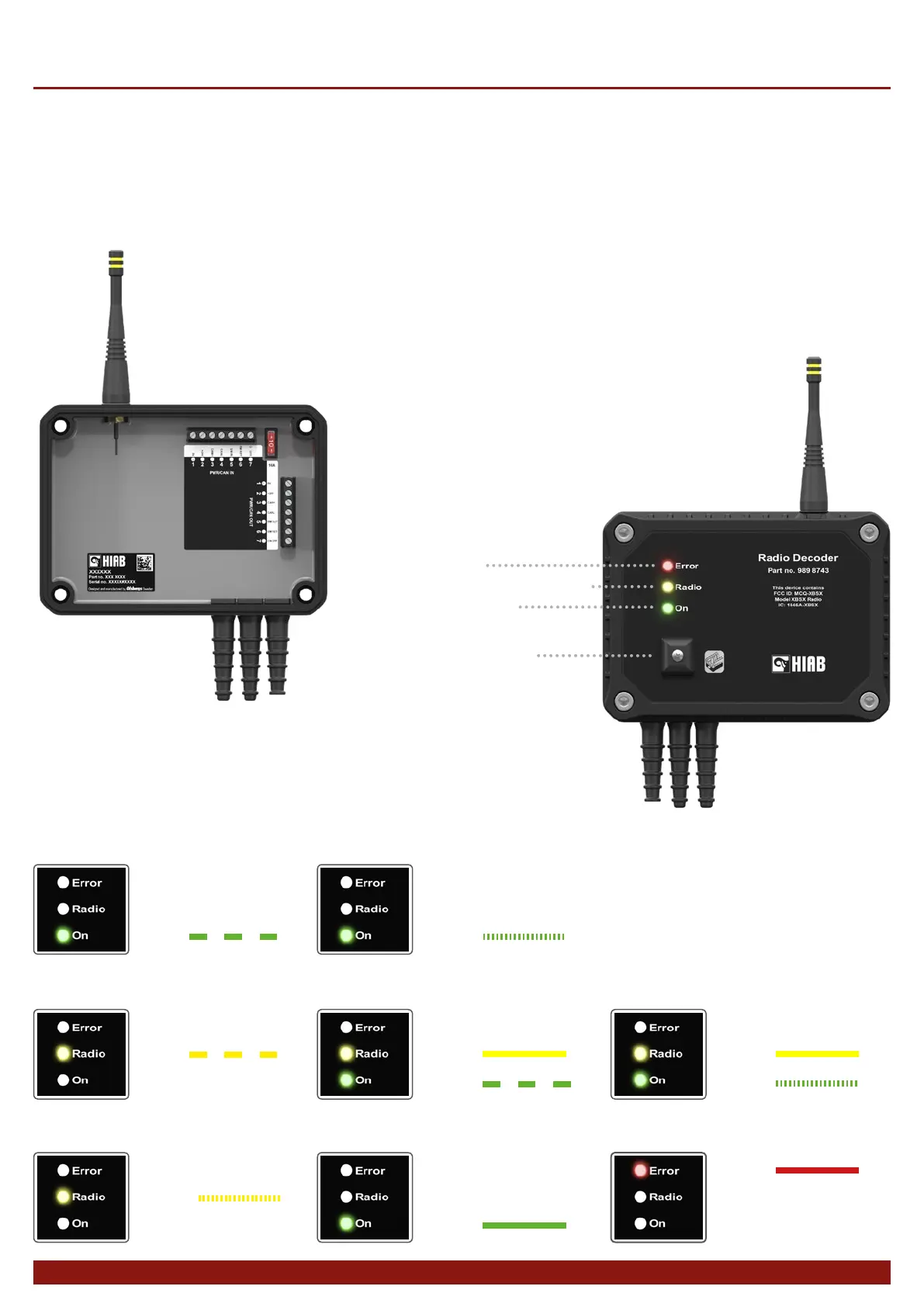
The radio decoder contains one of the radio
units. The decoder translates the radio trafc,
consisting of lever and button data from the
hand controller, to the CAN bus.
Blink mode for each LED in different operating cases:
4
Radio Decoder
Blink:
0,6s 1s 1s0,6s etc.
Decoder on, under initialisation:
Decoder powered,
no radio connection:
Pairing procedure in progress:
Blink:
0,6s 1s 1s0,6s etc.
20Hz
Flicker:
Cable operation:
Radio connection present,
safety requirements not met:
Pairing procedure complete:
Normal operation:
Internal error or failed
pairing procedure:
20Hz
Flicker:
Blink:
Steady:
0,6s 1s 1s0,6s etc.
Steady:
20Hz
Flicker:
Steady:
Steady:
LED L1: Fault status
LED L2: Radio communication status
LED L3: Radio control on
Connector controller cable
Technical description
For safety reasons, it is extremely important that
data is not corrupted, therefor the decoder has
dual micro-processors which monitor each other to
ensure accuracy in the translation. The controller
and the decoder must be “paired” with each other
to establish a connection. A unique code is loaded
and stored in each unit. The pairing procedure is
described elsewhere in this documentation.