4
INSTALLATION REQUIREMENTS
Introduction
Please read these instructions completely and carefully before install-
ing and operating the furnace.
MODELS HTL-D AND HTLV-D
Models HTL-D and HTLV-D are oil red forced air up-ow furnaces
with an output capacity range of 89,000 BTU/Hr. to 140,000 BTU/
Hr.
!
CAUTION
DO NOT USE GASOLINE, CRANK CASE OIL, OR ANY
OIL CONTAINING GASOLINE.
FOR YOUR SAFETY:
DO NOT STORE OR USE GASOLINE OR OTHER
FLAMMABLE VAPORS AND LIQUIDS IN THE VICIN-
ITY OF THIS OR ANY OTHER APPLIANCE.
All models are CSA listed, (NRTL/C) for use with No. 1 (Stove) and
No. 2 (Furnace) Oil. Please refer to the tables on page 11 (Oil Burner
Setups) of this manual for performance and dimensional data.
In Canada, the installation of the furnace and related equipment
shall be installed in accordance with the regulations of CAN/CSA
- B139, Installation Code for Oil-Burning Equipment, as well as in
accordance with local codes.
In the United States of America, the installation of the furnace and
related equipment shall be installed in accordance with the regula-
tions of NFPA No. 31, Standard for the Installation of Oil-Burning
Equipment, as well as in accordance with local codes.
Regulations prescribed in the National Codes and Local regulations
take precedence over the general instructions provided in this instal-
lation manual. When in doubt, please consult your local authorities.
All models are shipped assembled and pre-wired. e furnace should
be carefully inspected for damage when being unpacked.
Heat Loss
e maximum hourly heat loss for each heated space shall be calcu-
lated in accordance with the procedures described in the manuals of
the Heating, Refrigeration and Air Conditioning Institute of Canada
(HRAI), or by other means prescribed, or approved by the local
authority having jurisdiction.
In the United States, Manual J. titled, "Load Calculation" published
by the Air Conditioning Contractors of America, describes a suitable
procedure for calculating the maximum hourly heat loss.
Location of Unit
e furnace should be located such that the ue connection to the
chimney is short, direct and consists of as few elbows as possible.
When possible, the unit should be centralized with respect to the
supply and return air ductwork. A central location minimizes the
trunk duct sizing. All models may be installed on combustible oors.
e minimum installation clearances are listed in
Table 1
.
Location
Clearance to Combustibles
HTL-D and HTLV-D
Up ow
Top 1"
Bottom 0* Combustible Floor
S /A Plenum 1"
Rear 1"
Sides 1"
Front 1" **
Flue Pipe 9"
Enclosure Closet
* No carpet or vinyl
** 24 in. Required for service clearance
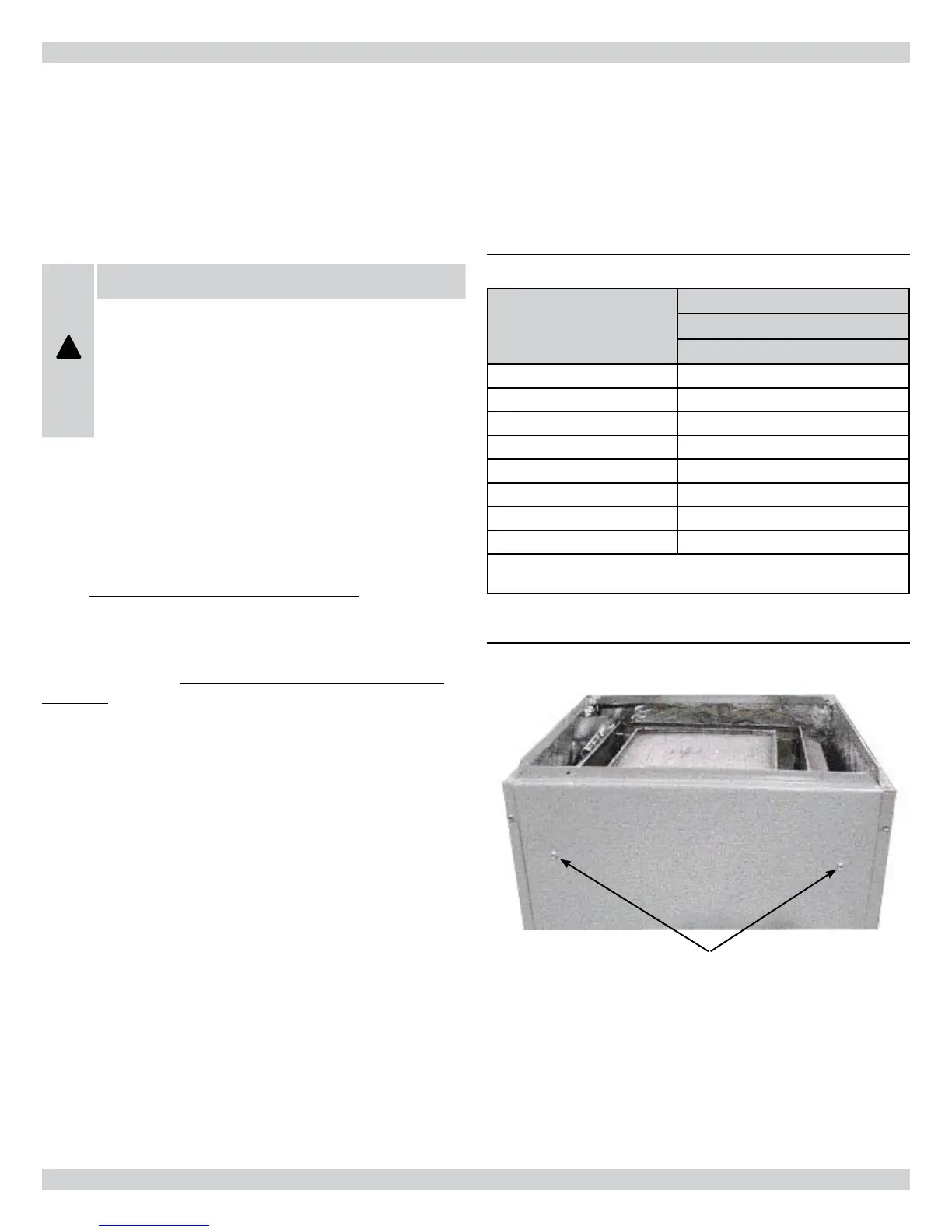
HEAT EXCHANGER SUPPORT SCREWS
Before nal placement of the furnace, the heat exchanger support
screws should be removed (See
Figure 1
). is may be preferable
if the furnace rear panel will be inaccessible aer installation. e
screws must be removed if the heat exchanger needs to be removed
from the cabinet.
Table 1 - Clearances
Figure 1 - Heat Exchanger Support Screws