5
LOCATION OF THE UNIT
Air Conditioning Applications
If the furnace is used in conjunction with air conditioning, the fur-
nace shall be installed in parallel with or upstream from the evapora-
tor coil to avoid condensation in the heat exchanger. In a parallel in-
stallation, the dampers or air controlling means must prevent chilled
air from entering the furnace. If the dampers are manually operated,
there must be a means of control to prevent the operation of either
system unless the dampers are in the full heat or full cool position.
e air heated by the furnace shall not pass through a refrigeration
unit unless the unit is specically approved for such service.
e blower speed must be checked and adjusted to compensate for
the pressure drop caused by the evaporator coil. Refer to page 18 of
this manual, for recommended wiring and electrical connections of
the air conditioning controls.
Combustion Air
If the furnace is installed in a closet or utility room, two openings
must be provided connecting to a well-ventilated space (full base-
ment, living room or other room opening thereto, but not a bed-
room or bathroom). One opening shall be located above the level of
the upper vent opening and one opening below the combustion air
inlet opening in the front of the furnace. Each opening shall have
a minimum free area of 1½ square inches per 1,000 Btu/h of total
input rating of all appliances installed in the room.
For furnaces located in buildings of unusually tight construction,
such as those with high quality weather stripping, caulking, windows
and doors, or storm sashed windows, or where basement windows
are well sealed, a permanent opening communicating with a well
ventilated attic or with the outdoors shall be provided, using a duct
if necessary. e duct opening shall have a free area of 1½ square
inches per 1,000 Btu/h of total input rating of all appliances to be
installed. When a furnace is installed in a full basement, inltration
is normally adequate to provide air for combustion and dra opera-
tion. Furnace rooms under 65m³ (2295
3
) should automatically be
treated as conned space.
Chimney Venting
e ue pipe should be as short as possible with horizontal pipes
sloping upward toward the chimney at a rate of one-quarter inch to
the foot. e ue pipe should not be smaller in cross sectional area
than the ue collar on the furnace. e ue pipe should connect to
the chimney such that the ue pipe extends into, and terminates
ush with the inside surface of the chimney liner. Seal the joint
between the pipe and the lining. e chimney outlet should be at
least two feet above the highest point of a peaked roof. All unused
chimney openings should be closed. Chimneys must conform to
local, provincial or state codes, or in the absence of local regulations,
to the requirements of the National Building Code.
NOTICE
THE FURNACE IS APPROVED FOR USE WITH TYPE L
VENT OR EQUIVALENT.
!
CAUTION
CHIMNEY VENTED VERSIONS OF THE FURNACE
MUST BE CONNECTED TO A FLUE HAVING SUFFI-
CIENT DRAFT AT ALL TIMES TO ENSURE SAFE AND
PROPER OPERATION OF THE APPLIANCE.
NOTICE
THE RECOMMENDED FLUE DRAFT PRESSURE IS
-0.02 IN. W.C. (See
Figure 2
)
e ue pipe must not pass through any oor or ceiling, but may
pass through a wall where suitable re protection provisions have
been installed. Refer to the latest edition of CAN/CSA B-139 for
rules governing the installation of oil burning equipment. In the
United States, refer to the latest edition of NFPA 31 for regulations
governing the installation of oil burning equipment.
See Page 11, (Oil Burner Setups) of this manual for burner set-up.
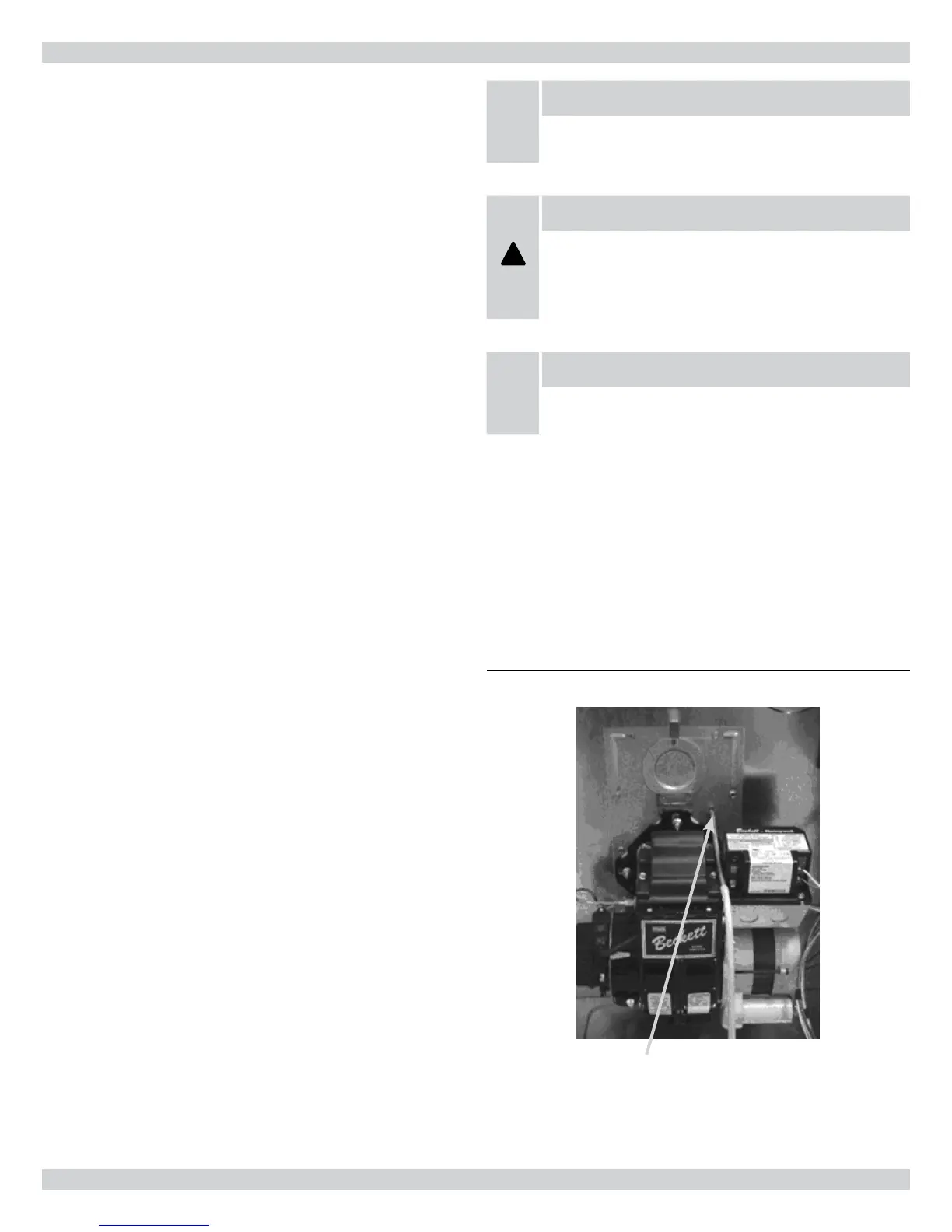
Figure 2 - Checking Over-Fire Draft
Over-re dra access port