6
CONTROLS & CONNECTIONS
Barometric Damper Control
e barometric damper control, also known as a dra regulator,
is used on conventional chimney venting only. is control auto-
matically maintains a constant negative pressure in the furnace to
obtain maximum eciency. It ensures that proper pressures are
not exceeded. If the chimney does not develop sucient dra, the
dra control cannot function properly. e dra regulator, when
installed should be in the same room or enclosure as the furnace and
should not interfere with the combustion air supplied to the burner.
e control should also be located near the furnace ue outlet and
installed according to the instructions supplied with the regulator.
e ue outlet pressure (measured between the furnace and dra
regulator, or the oil burner mounting plate over-red dra access
port ,
Figure 2
) should be set to -0.02 in. w.c.
Fan Timer Board and Limit Control (FIG. 4) (page 21)
e Electronic Fan Timer integrates control of all burner and circu-
lator fan operations. is control is the central wiring point for most
of the electrical components in the furnace. e United Technolo-
gies 1158-120 (HTL-D) has an adjustable fan on time that is set by
selecting the dipswitch combination displayed in
Table 2
. is
fan on delay can be set at 30, 60 90 or 120 seconds. is provides a
delay between the burner ignition and blower start-up to eliminate
excessive ow of cold air when the blower comes on. e United
Technologies 1158-120 (HTL-D) has an adjustable fan o time of 1,
2, 4 or 6 minutes displayed in
Table 2
. e fan o delay time starts
when the burner motor is de-energized at the end of a call for heat.
Blower shutdown is delayed to remove any residual heat from the
heat exchanger and improve the annual eciency of the furnace.
e electronic fan timer board works in conjunction with snap disc
limit controls, which perform a safety function, and breaks power
to the oil burner primary control, which shuts o the burner if the
furnace over-heats. e limit control is thermally operated and
automatically resets. e limit control is factory installed, pre-set and
is not adjustable.
If the limit control opens with the United Technologies 1158-120
(HTL-D) electronic fan control, the circulating fan will be energized
as well. When the limit closes, the fan o timer will begin. At the
end of the fan o time cycle the burner will be energized, initiating a
normal burner cycle.
Fan Timer Board and Limit Control (Fig. 5) (Page 21)
e United Technologies 1168-1 ECM (HTLV-D) tap board has an
adjustable fan on/o delay that must be adjusted in accordance with
the furnace input rating (nozzle size).
Refer to Tables 8A and 8B
(pg 16 and 17)
for ECM blower set-up.
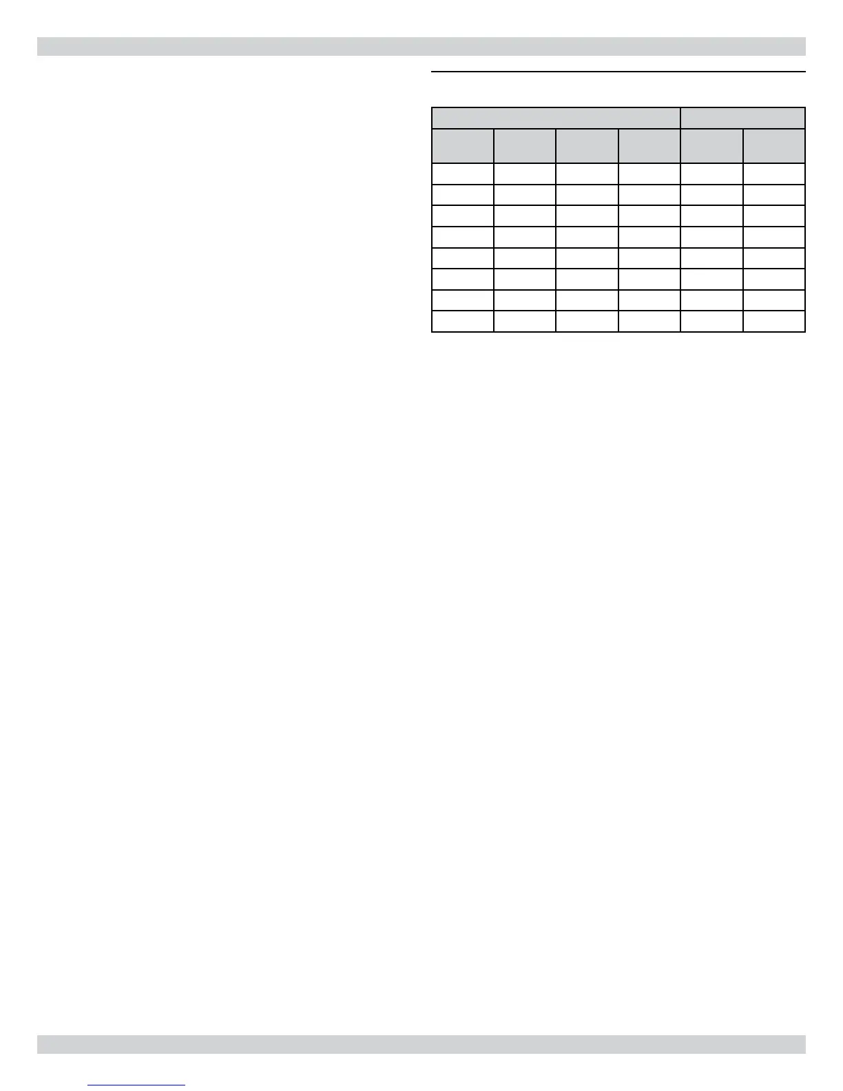
Table 2 - United Technologies 1158-120 (HTL-D)
Dip Switch Position Blower Delay Times
1 2 3 4
ON
Seconds
OFF
Minutes
O O 30
On O 60
O On 90
On On 120
O O 1
On O 2
O On 4
On On 6
Electrical Connections
e furnace is listed by the Canadian Standards Association un-
der the NRTL (North American) Standard. It is factory wired and
requires minimal eld wiring. All eld wiring should conform to
CAN/CSA C22.1 Canadian Electrical Code, Part 1, and by local
codes, where they prevail. In the United States, the wiring must be in
accordance with the National Fire Protection Association NFPA-70,
National Electrical Code, and with local codes and regulations.
e furnace should be wired to a separate and dedicated circuit in
the main electrical panel; however, accessory equipment such as
electronic air cleaners and humidiers may be included on the fur-
nace circuit. Although a suitably located circuit breaker can be used
as a service switch, a separate service switch is advisable. e service
switch is necessary if reaching the circuit breaker involves becoming
close to the furnace, or if the furnace is located between the circuit
breaker and the means of entry to the furnace room. e furnace
switch (service switch) should be clearly marked, installed in an eas-
ily accessible area between the furnace and furnace room entry, and
be located in such a manner to reduce the likelihood that it would be
mistaken as a light switch or similar device.
e power requirement for the HTL-D and HTLV-D models is: 120
VAC, 1 Ø, 60 Hz., 12A.
Accessories requiring 120 VAC power sources such as electronic
air cleaners and humidier transformers may be powered from the
electronic fan timer board where provisions have been made for con-
nections, but should have their own controls. Do not use the direct
drive motor connections as a power source, since there is a high risk
of damaging the accessories by exposure to high voltage from the
auto-generating windings of the direct drive motor.
ermostat wiring connections and air conditioning contactor low
voltage connections are shown in the wiring diagrams on page 18 of
this manual. Some micro-electronic thermostats require additional
controls and wiring. Refer to the thermostat manufacturer's instruc-
tions.