3
ASSEMBLY
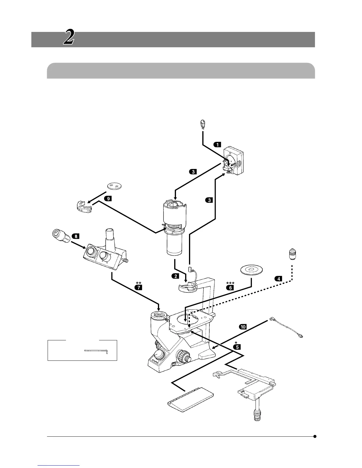
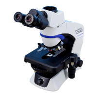
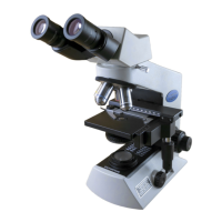
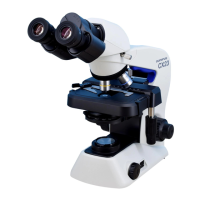
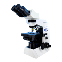
2-1 Assembly Diagram
The diagram below shows the assembly sequence for the various modules. The numbers indicate the order of assembly.
# When assembling the equipment, make sure that all parts are free of dust and dirt. Avoid scratching any parts or glass
surfaces.
# Keep the provided Allen wrench on hand. You will need it when replacing the modules.
Allen wrench
Required tool
* Can also be mounted on the
left side. However, the mechani-
cal stage cannot be mounted
in the same position as the
stage extension plate.
** The CK30 is provided with sta-
tionary binocular tube.
Halogen bulb
6V 30W HAL
Lamp socket
U-LS30-3
Filter
Filter holder
Transmitted
illumination
unit
Stage plate
· Standard stage plate
· CK40-CPG
· IX-CP50
Objective
Eyepiece
· NCWHK10X
· WHK10X
· WHK15X
Observation tube
· CH3-BI45
· CH3-TR45
· CK40-TBI
Power cord
Microscope body
· CK30-F
· CK40-F
Stage extension plate
CK2-SS
Mechanical stage
CK40-MVR
***The CK30 is not provided with
a stage plate.