7
5
7
0
6
0
5
0
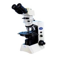
(3) Optical axis (CKX41)
7
5
7
0
6
0
5
0
Adjustment (A)
Adjustment (B)
Adjustment (C)
*3
*4
*5
Adjustment (A) : Loosen the screws(*3) and adjust the revolving axis by moving the right sleeve.
Screw: CUK3X6SB 2pcs. (*3)
Adjustment (B ) : Loosen the screws(*4) and adjust the left /right optical axis by moving the left
sleeve. (the right sleeve is taken as a standard)
Adjustment ( C) : Loosen the screws(*5) and adjust the absolute optical axis in the right sleeve
Screw: CUK3X6SB 2pcs. (*4)
by moving the position of binocular unit.
Screw: CUKK3X6SA 4pcs. (*5)
*1
*2
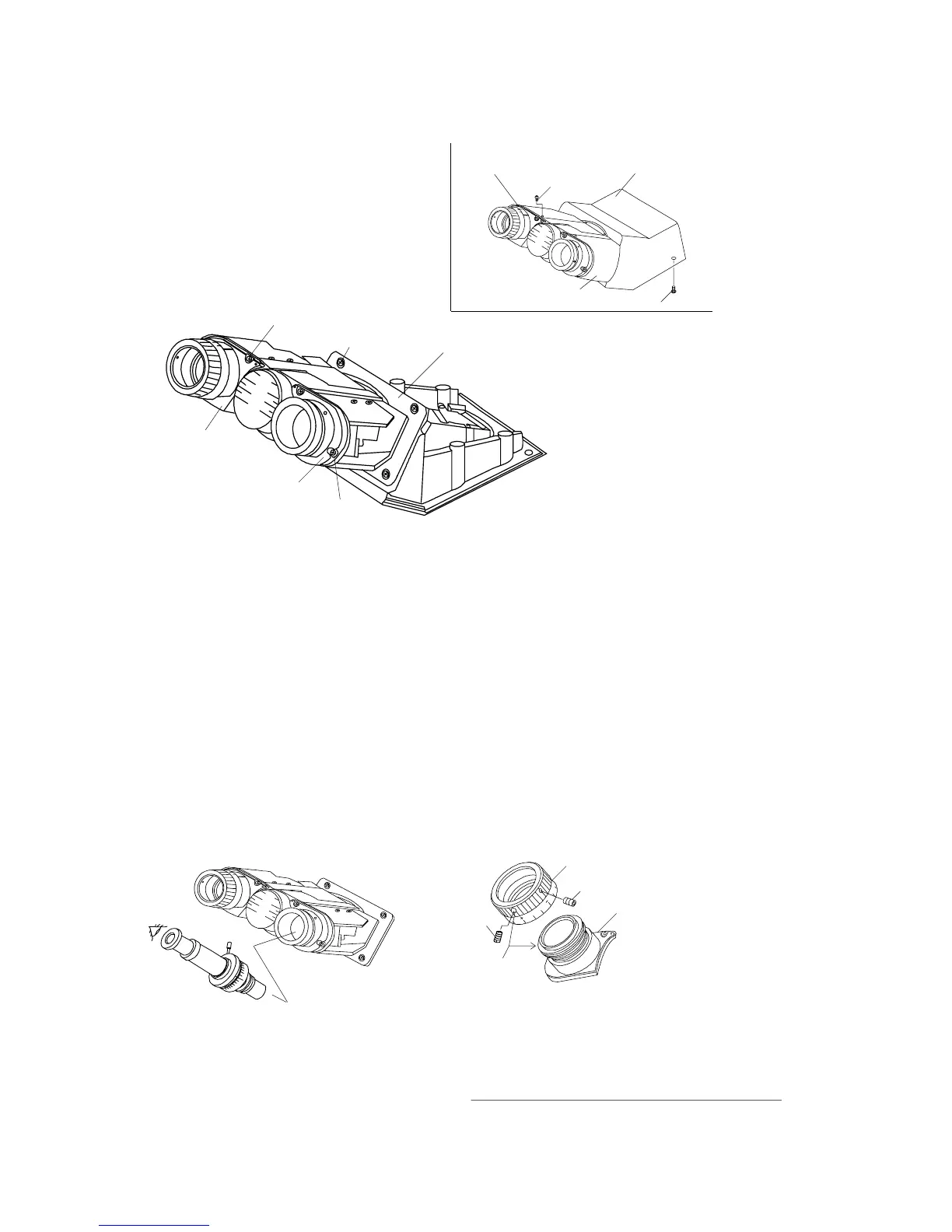
1) Remove the cover-L and cover-R.
Screw: 3PUTB2X4SB 3pcs. each (*1)
2) Remove the cover.
Screw: CUTB3X10SA 2pcs. (*2)
Cover
Cover-L
Cover-R
<Fig.2>
<Fig.2>
(4) Parfocality <CKX41>
*In the same manner as CKX31, adjust the paforcality by inserting washer under the lens frame-1.
(For adjustment procedure, refer to D-12.)
*2
*1
<Left sleeve>
After checking it in the right sleeve, turn the
helioid to focus on the specimen in KN0041,
then loosen the screws(*1) ,only move the
scale ring and fix it at the position where
scale “0” is aligned to the index.
7
5
7
0
6
0
5
0
Insert the jigs in the right sleeve and check
the parfocality.
1) Focusing telescope
(FT-36 or U-FT)
Jigs:
2) Standard eyepiece
(KN0048; Adapter-1)
3) Standard objective(KN0041)
D-2
CKX31/CKX41 D. REPAIR PROCEDURE
Note: When using the screw(*2) for fixing eyepiece;
mount the diopter ring with (A) and (B) screw
hole positions aligned without the above
adjustment.
0
Helicoid ass’y (B)
Diopter ring (A)
(Positions of
screw holes)