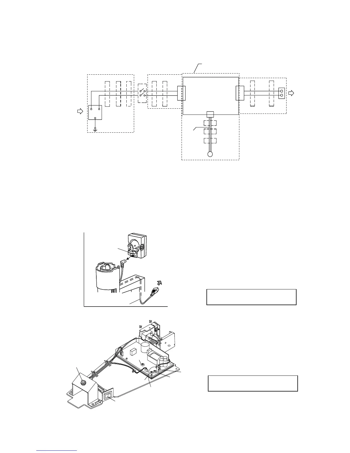
CN3
Dimmer Cont
CN1
CN2
U003
1
2
6V30W
Halogen
Lamp
U002
1
3
E
N
L
INPUT
100-120/
220-240VAC
50/60Hz
U203
U103
1
3
2
4
S001
E005
E001
E003
E002 E003
E004
E002
E003
E006
U001
E002
Circuit board
Circuit board ass'y
(AQ828900)
Rheostat
ass'y
(DZ308400)
(DZ308500)
U004
E001: Ferrite core
E002-E006: Binder
4. Electrical Unit
4-1 CKX31/CKX41 connecting diagram
4-2 Voltage adjustment
The circuit board ass’y (AQ828900) consists of the circuit board(DZ308400) and rheostat ass’y
(DZ308500). In case where the above parts are replaced as AQ828900, the voltage adjustments for
the circuit board ass’y are not necessary. However, voltage adjustments are necessary when
individually replacing either the circuit board(DZ308400) or rheostat ass’y(DZ308500). The
following explains procedures for voltage adjustments. For replacing circuit board/rheostat ass’y,
refer to disassembly and assembly procedures on C-13 to C-14.
A
A
Power cord
VR21
VR22
VR23
6V30W
halogen
bulb
Lamp cable
(a)
Minimum voltage adjustment
1) Turn ON the power. Turn the light
Power switch
Set the digital multimeter
to CN2 2-pin
CN2
intensity control part (a) cunterclock-
wise to lower lamp brightness to its
lowest level.
2) Rotate the circuit board’s trimmer VR21
between the CN2’s 1 and 2 pins is within
to adjust so that the lamp output voltage
the standard shown below using a digital
multimeter.
Standard: DC1.10 - 1.15V
(adjustment target: 1.123V)
1) Turn ON the power. Turn the light
intensity control part (a) clockwise
to increase lamp brightness to its highest
level.
the standard shown below using a digital
multimeter.
Standard: DC5.65 - 5.75V
(adjustment target: 5.70V)
Maximum voltage adjustment
2) Rotate the circuit board’s trimmer VR23
to adjust so that the lamp output voltage
between the CN2’s 1 and 2 pins is within
* Do not turn the trimmer VR22 mounted on
circuit board because it is adjusted to the
prescribed current value.
(overcurrent protection)
CKX31/CKX41 D. REPAIR PROCEDURE
D-14