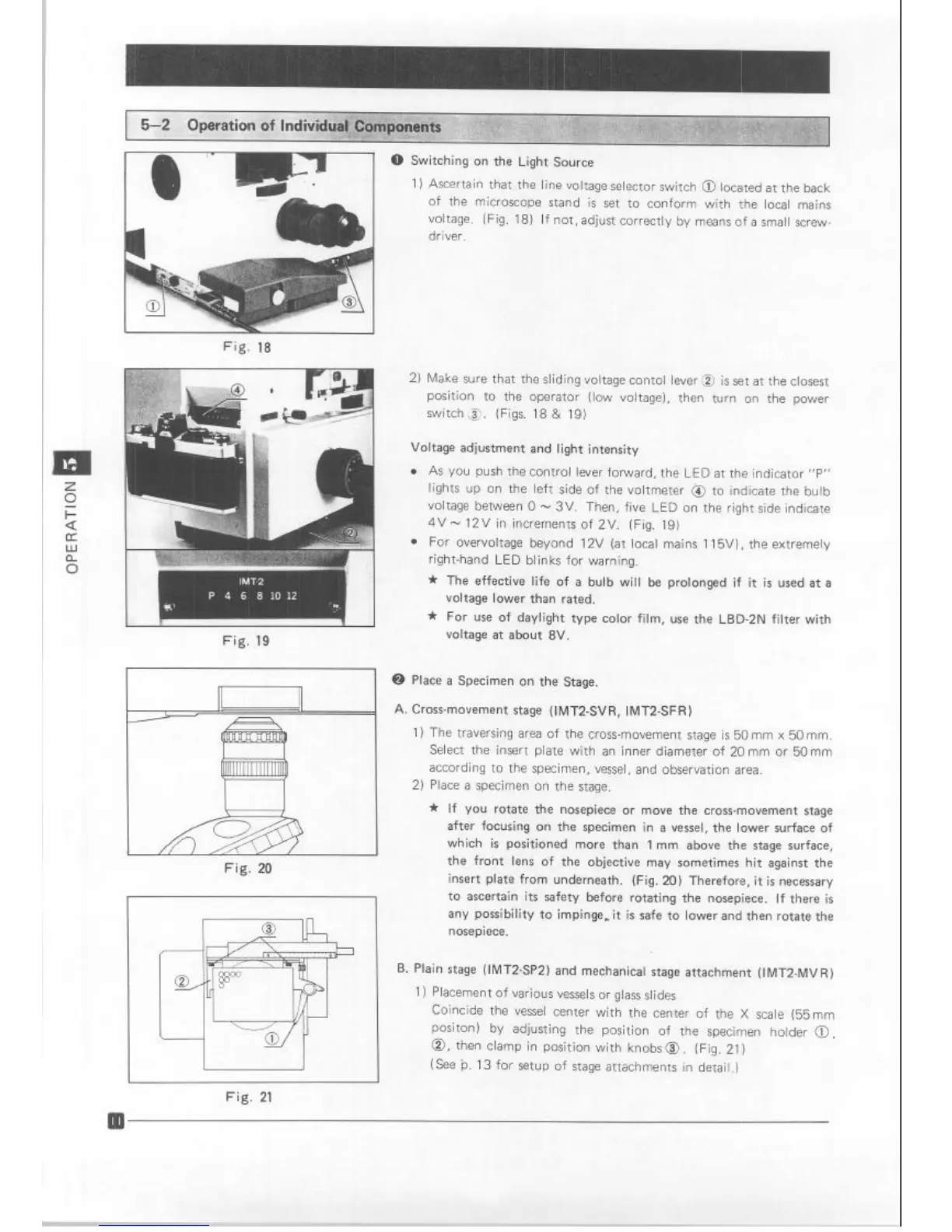
0 Switching on the Light Source
1) AscertaIn that the line voltage selector switch @ located at the back
of the microscope stand is set to conform with the local mains
voltage. (Fig. 18) If not, adjust correctly by means of a small screw-
driver.
I
Fig. 19
Fig. 20
2) Make sure that the sliding voltage contol lever @ is set at the closest
position to the operator (low voltage), then turn on the power
switch3. (Figs. 18 & 19)
Voltage adjustment and light intensity
l
As you push the control lever forward, the LED at the indicator “P”
lights up on the left side of the voltmeter @ to indicate the bulb
voltage between 0 - 3V. Then, five LED on the right side indicate
4V- 12V in increments of 2V. (Fig. 19)
l
For overvoltage beyond 12V (at local mains 115V). the extremely
right-hand LED blinks for warning.
* The effective life of a bulb will be prolonged if it is used at a
voltage lower than rated.
* For use of daylight type color film, use the LBD-2N filter with
voltage at about 8V.
@ Place a Specimen on the Stage.
A. Cross-movement stage (IMT2-SVR, IMT2SFR)
1) The traversing area of the cross-movement stage is 50 mm x 50 mm.
Select the insert plate with an inner diameter of 20 mm or 50 mm
according to the specimen, vessel, and observation area.
2) Place a specimen on the stage.
* If you rotate the nosepiece or move the cross-movement stage
after focusing on the specimen in a vessel, the lower surface of
which is positioned more than 1 mm above the stage surface,
the front lens of the objective may sometimes hit against the
insert plate from underneath. (Fig. 20) Therefore, it is necessary
to ascertain its safety before rotating the nosepiece. If there is
any possibility to impinge-it is safe to lower and then rotate the
nosepiece.
B. Plain stage (IMT2-SP2) and mechanical stage attachment (lMT2-MVR)
1 ) Placement of various vessels or glass slides
Coincide the vessel center with the center of the X scale (55mm
positon) by adjusting the position of the specimen holder 0,
0, then clamp in position with knobs 0. (Fig. 21)
(See b. 13 for setup of stage attachments in detail.)
Fig. 21
II
Artisan Technology Group - Quality Instrumentation ... Guaranteed | (888) 88-SOURCE | www.artisantg.com
 Loading...