Installation and Connection
2
2.4 Connection of the 3CCD Camera Control Unit (OTV-SP1C or OTV-SP1C-G)
18
2.4 Connection of the 3CCD Camera Control Unit
(OTV-SP1C or OTV-SP1C-G)
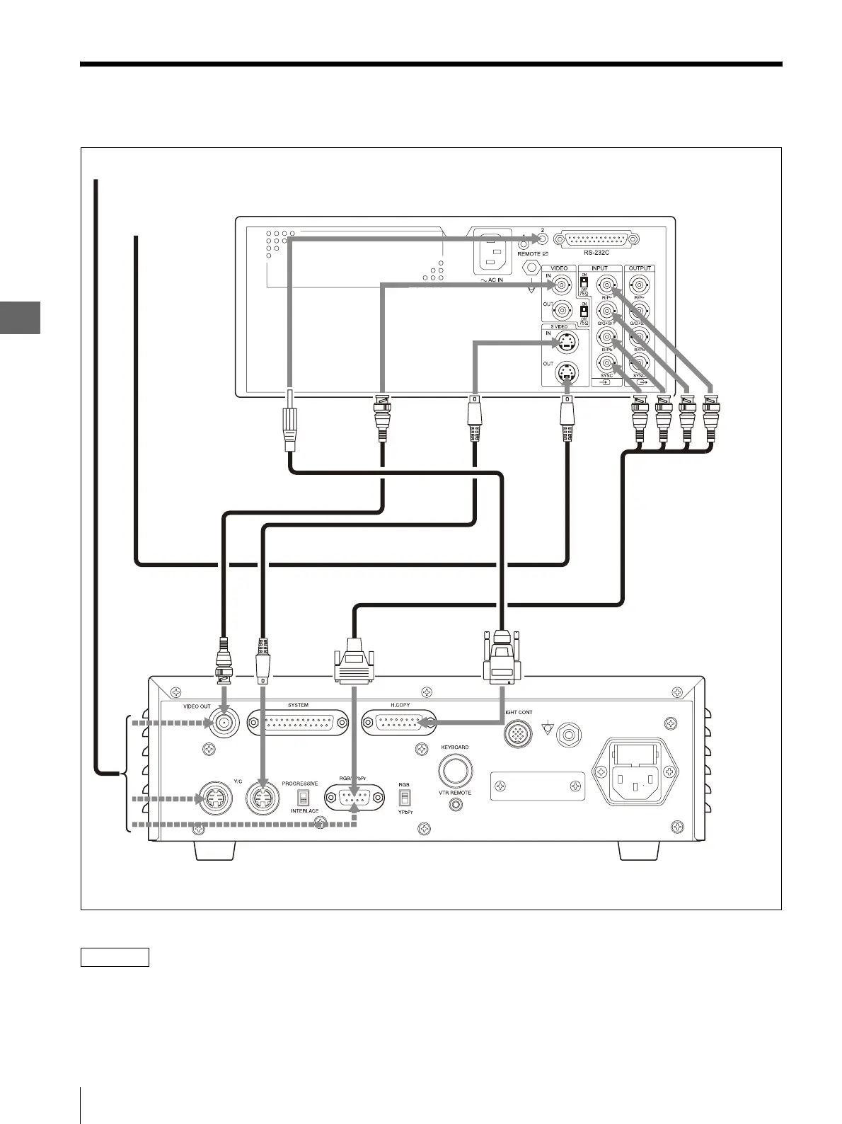
Figure 2.3
NOTE
• It can be used if any one of an RGB cable, a Y/C cable,
and the BNC cable is connected between this
instrument and 3CCD camera control unit (OTV-
SP1C, OTV-SP1C-G).
• Refer to the instruction manual of 3CCD camera
control unit (OTV-SP1C, OTV-SP1C-G) for
connection of 3CCD camera control unit (OTV-SP1C,
OTV-SP1C-G) and the monitor.
Color Video Printer (OEP-4)
S VIDEO OUT
terminal
S VIDEO IN
terminal
RGB cable (MH-984)
Y/C cable (MH-985)
Y/C cable
3 CCD Camera Control Unit
(OTV-SP1C, OTV-SP1C-G)
To a monitor
BNC cable (MB-677)
To Y/C input connector
of a monitor
OEP cable (MH-987)
Y/C
terminal
VIDEO OUT
(video output)
terminal
H.COPY (Hard copy)
terminal
RGB/YPbPr output
terminal
VIDEO IN
terminal
REMOTE 2
terminal
INPUT
terminals
SBGR