Instrument Nomenclature and Functions
1
1.3 Rear Panel
12
1.3 Rear Panel
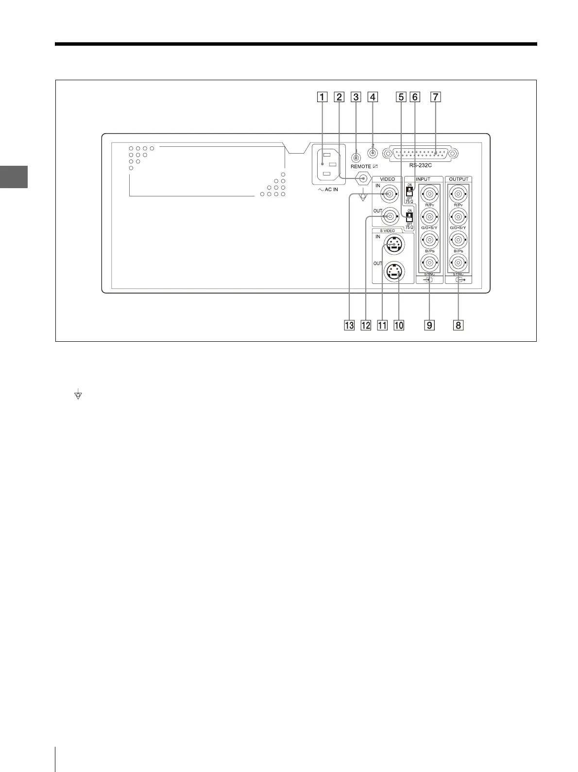
A Power inlet
Connect the power cord for AC power supply.
B Equipotential terminal
For safety, connect this terminal to the equipotential
bus bar of the hospital.
C REMOTE 1 terminal
When using the provided remote control unit
(MAJ-898) for wired remote control of this
instrument, connect the remote control unit here.
D REMOTE 2 terminal
When communication with the camera control unit
is required, connect the OEP cable (MH-987) or
remote cable (MH-907) here.
E Composite 75 Ω termination switch
Set to ON to terminate the composite video signal.
F RGB 75 Ω termination switch
Set to ON to terminate the RGB signals.
G RS-232C terminal
When communication with the video system center
is required, connect the remote cable (MH-995 or
MH-877) here.
H OUTPUT (RGB video output) terminals
Output the RGB video signals to a connected
equipment such as a monitor.
Either the SDTV or HDTV signals can be output.
I INPUT (RGB video input) terminals
Input the RGB video signals from a connected
equipment such as the video system center or
monitor.
Either the SDTV or HDTV signals can be output.
J S VIDEO OUT (output) terminal
Outputs the S-Video signal to a connected
equipment such as a monitor.
K S VIDEO IN (input) terminal
Inputs the S-Video signal from a connected
equipment such as the video system center or
monitor.
L VIDEO OUT (Composite video output) terminal
Outputs the composite video signal to a connected
equipment such as a monitor.
M VIDEO IN (Composite video input) terminal
Inputs the composite video signal from a connected
equipment such as the video system center or
monitor.