OEV262H
2. Location and Function of Parts and Controls
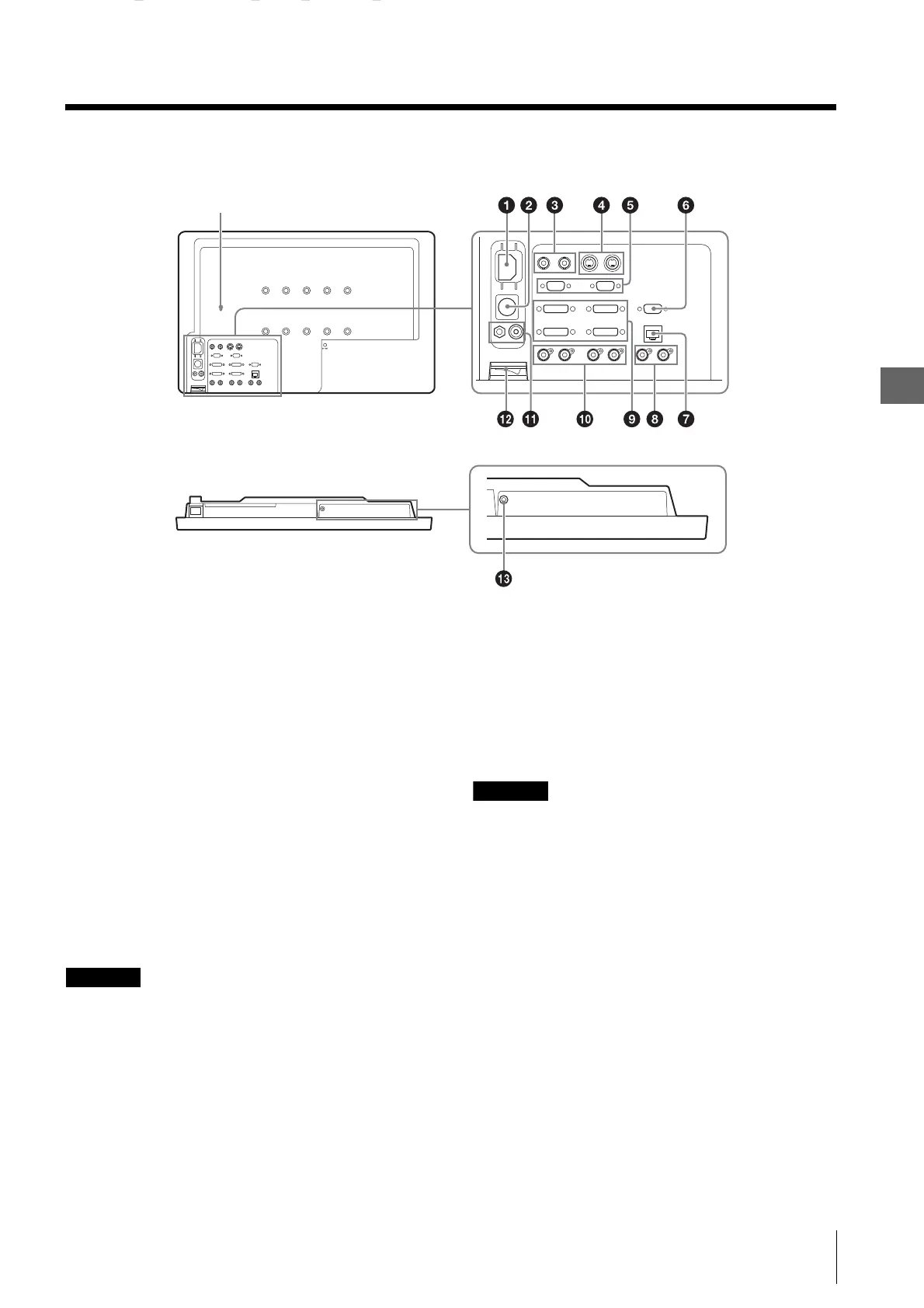
2.3 Rear Panel
17
2.3 Rear Panel
a AC IN socket
For the supplied AC power cord.
b DC 5V/24V IN connector
For the DC connector of the optional AC adapter.
c COMPOSITE input/output connector (BNC)
IN connector
Input connector for composite signals.
OUT connector
Loop-through output connector.
d Y/C input/output connector (4-pin mini-DIN)
IN connector
Input connector for Y/C signals.
OUT connector
Active through output connector.
CAUTION
• A signal is output from the OUT connector only when
the monitor is turned on. When the monitor is turned
off, the signal is not output from the OUT connector.
• Be sure to connect the equipment or cable specified by
this operating instructions to the OUT connector. If
you connect the equipment or cable that is not
specified by this operating instructions to the OUT
connector, the monitor may affect the operation of the
connected equipment.
e HD15 input/output connector (D-sub 15-pin,
female)
The Plug & Play function corresponds to DDC2B.
IN connector
Input connector for HD15 signals.
OUT connector
Active through output connector.
CAUTION
• A signal is output from the OUT connector only when
the monitor is turned on. When the monitor is turned
off, the signal is not output from the OUT connector.
• Be sure to connect the equipment or cable specified by
this operating instructions to the OUT connector. If
you connect the equipment or cable that is not
specified by this operating instructions to the OUT
connector, the monitor may affect the operation of the
connected equipment.
f SERIAL REMOTE RS-232C connector (D-sub
9-pin, female)
Connect to the RS-232C control connector on external
equipment connected to the monitor. The monitor can be
operated according to control commands sent from
connected external equipment.