VII. USE OF OPTIONAL ACCESSORIES
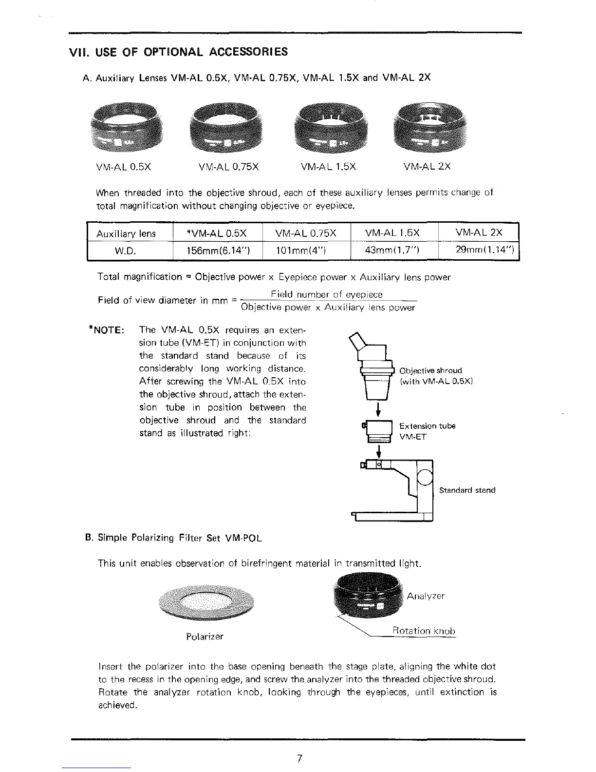
A. Auxiliary
Lenses
VM-AL
0.5X,
VM-AL
0.75X,
VM-AL
1.5X
and
VM-AL
2X
VM-AL
0.5X
V
M-AL
0.75X
VM-AL
1.5X
VM-AL
2X
When
threaded
into
the objective shroud,
each
of
these auxiliary
lenses
permits change
of
total magnification
without
changing objective
or
eyepiece.
Auxiliary
lens
*VM-AL
0.5X
VM-AL
0.75X
VM-AL
1.5X
W.D.
156mm(6.14")
101mm(4")
43mm(1.7")
Total magnification = Objective power x Eyepiece power x
Auxiliary
lens power
F
.
Id f ·
d"
. Field number
of
eyepiece
1e
o
v1ew
1ameter
1n
mm = -
-----···--;'-~---
Objective power x
Auxiliary
lens power
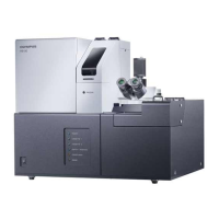
*NOTE:
The
VM-AL
0.5X requires
an
exten-
sion tube (V M-ET) in conjunction
with
the
standard stand because
of
its
considerably long working distance.
After
screwing the
VM-AL
0.5X
into
the
objective shroud, attach
the
exten-
sion
tube
in
position between the
objective
shroud
and
the
standard
stand
as
illustrated right:
Extension tube
VM-ET
VM-AL
2X
29mm(1.14")
r
l
~
Standecd
stand
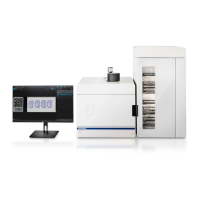
B.
Simple Polarizing Filter Set VM-POL
This
unit
enables observation
of
birefringent material in
transmitted
light.
Analyzer
Polarizer
Rotation
Insert the polarizer
into
the
base
opening beneath the
stage
plate, aligning the
white
dot
to
the
recess
in
the
opening
edge,
and screw the analyzer
into
the threaded objective shroud.
Rotate the analyzer
rotation
knob,
looking
through
the
eyep-Ieces,
until exf1nction
"1s
achieved.
7