L1581IENS007
19
7.0.
MESSA IN SERVIZIO
Ogni danno derivante dalla mancata
osservanza delle seguenti indicazioni
non sarà addebitabile al costruttore e
causa la decadenza della garanzia.
Scegliere il luogo di installazione
osservando le norme vigenti in materia di
sicurezza del lavoro.
PERICOLO
!
7.1.
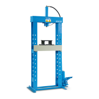
Area di installazione
Nell'individuazione dell'area di installazione si deve tener
conto dell'ingombro massimo della pressa (vedi § 4.0. - DA-
TI TECNICI) e si deve considerare lo spazio praticabile
dall'operatore intorno al perimetro dell’apparecchio
(rispettare una distanza di almeno 800 mm da ogni parte
della pressa, da eventuali pareti o da qualunque attrezzatura
al fine di consentire le necessarie operazioni di manutenzio-
ne e controllo).
Per definire l’area di installazione della macchina verificare
le misure di ingombro § 4.0. - DATI TECNICI.
La pressa deve essere installata in modo che dalla po-
stazione di comando l'operatore sia in grado di visualiz-
zare tutto l'apparecchio e l'area circostante in modo da
verificare, in tale area, l'assenza di persone esposte e/o
di oggetti potenziali fonti di pericolo.
Requisiti minimi per il pavimento
La pressa deve essere posizionata su di un piano orizzonta-
le preferibilmente cementato o piastrellato. Evitare piani ce-
devoli o sconnessi.
Il calcestruzzo utilizzato per la pavimentazione deve avere
una resistenza cubica di RcK 35 N/mm
2
, la classe del calce-
struzzo deve essere C28/C35, con profondità di almeno 150
mm.
Failure to apply the following instructions
could lead to the expiration of the
guarantee conditions and relieve the
manufacturer of all and any responsibility
for possible damage caused by using the
equipment.
Choose the place of installation
observing the regulations in force relative
to safety at work.
WARNING
!
7.0.
START UP
7.1.
Installation area
When identifying the installation area, account must be tak-
en of the overall size of the press (see § 4.0. – TECHNICAL
DATA), the practicable space for the operator around the
perimeter of the machine must be taken into consideration
(keep a minimum 800 mm distance from every part of the
press, from walls or any other equipment so as to allow the
necessary maintenance and checking operations).
Check the overall dimensions § 4.0 to define the machine’s
installation area. - TECHNICAL DATA.
The press must be installed so that the operator can see
the whole of the machine and the surrounding area from
the control post so as to be able to check that, in that
area, there are no exposed people and/or objects that
could be a source of danger.
Minimum requisites for the floor
The press must be positioned on a horizontal surface that is
preferably cemented or tiled. Avoid weak or unsteady surfac-
es.
The concrete used for the bottom flooring must have a cubic
resistance equivalent to 35 N/mm
2
RcK. The concrete class
must be C28/C35, and be at least 150 mm deep.
Effettuare il fissaggio a terra della pressa, utilizzare quattro
tasselli (non in dotazione) con le seguenti caratteristiche:
diametro = 18 mm, lunghezza = 100 mm.
Forare per almeno 110 mm (1 TAV. 8) con punta
corrispondente al diametro del tassello (Ø 18 mm) nei
quattro punti di fissaggio (TAV. 9) predisposti sul
basamento.
Pulire il foro (2 TAV. 8).
Spingere ciascun tassello in ciascun foro con leggeri
colpi di martello (3 TAV. 8).
Stringere i bulloni con chiave dinamometrica, tarata a
70 N·m (4 TAV. 8). Se tale valore non permette il
bloccaggio dei tasselli la causa va ricercata nell'errata
foratura (diametro troppo grande) o nella insufficiente
consistenza del calcestruzzo della fondazione.
7.2.
Fissaggio a terra
È vietato utilizzare la pressa se questa
non è fissata al suolo.
PERICOLO
!
It is forbidden to use the press if it is not
fixed to the ground.
Fix the press to the floor using four anchor bolts (not
supplied) of the following specification: diameter = 18 mm,
length = 100 mm.
Drill for at least 110 mm (1 FIG. 8) with a bit
corresponding to the diameter of the anchor bolt
(Ø 18 mm) in the 4 fixing points (FIG. 9) provided on the
base.
Clean the hole (2 FIG. 8).
Push each anchor bolt into each hole with gentle
hammer-blows (3 FIG. 8).
Tighten the bolts with a dynamometric wrench calibrated
to 70 N·m (4 FIG. 8). If this value fails to tighten the bolts,
it may be caused by incorrect drilling (diameter too large)
or insufficient consistency of the concrete foundation.
7.2.
Fixing to the ground
DANGER
!
AVVERTENZA
!
L’installazione della macchina su
pavimenti sopraelevati o soprastanti
spazi vuoti deve essere autorizzata da
un qualificato tecnico delle costruzioni
civili, OMCN declina ogni
responsabilità.
WARNING
!
The installation of the machine on
raised floors or floors over empty
spaces must be authorized by a civil
construction technician. OMCN declines
all responsibility.