ii
CTXL High Performance Universal
Portable Circular Chart Recorder
TABLE OF
FIGURES
Figure Description Page
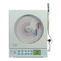
1-1 Front and Side Views of the Recorder -
Temperature/Humidity Model ................................................ 1-2
1-2 Wiring Diagram, Dual Process Input Model, CTXL-DPR .... 1-4
1-3 Rear and Side Views ................................................................... 1-5
1-4 Front and Side Views of the Recorder -
Dual Thermometer Model ......................................................... 1-5
1-5 Front View of the Recorder - Dual Process Input Model ...... 1-5
1-6 Membrane Keypad and Display Functions ............................ 1-6
2-1 Foot Cover Removal ................................................................... 2-1
2-2 Swiveling Stabilizing Arm ......................................................... 2-2
2-3a Stabilizing Arm Use for Bench Top Use
(Normal Position) ....................................................................... 2-2
2-3b Stabilizing Arm in Extended Position
(Position When You Open Door) .............................................. 2-2
2-4a Installing the Foot Cover (Top View) ...................................... 2-3
2-4b Installing the Foot Cover (Side View) ...................................... 2-3
2-5 Battery Compartment and Battery Orientation ...................... 2-4
2-6 Battery Warnings ........................................................................ 2-5
2-7 Changing Chart Speed and Scale Flow Diagram ................... 2-6
2-8 Changing Chart Paper and Setting the Time .......................... 2-7
2-9 Offset Alignment of Pens (For Ease of Pen Installation) ....... 2-7
2-10 Vertical Alignment of Pens (Pens Can’t Be Inserted) ............ 2-8
2-11 Pen Installation ............................................................................ 2-9
2-12 Pen Removal ................................................................................ 2-9
2-13 Setting Alarms and Time Clock .............................................. 2-10
2-14 Relay Terminal Block Wiring Diagram ................................. 2-11
2-15 Reviewing Parameter Values .................................................. 2-12
2-16 Using the Remote Sensor Cable .............................................. 2-13
2-17 Using the Sensor Clip for Mounting Sensor
in a Remote Location ................................................................ 2-14
2-18 pH Probe/RTD Connections ................................................... 2-16
3-1 Main Window Screen ................................................................. 3-7
3-2 Settings Menu - General Tab Screen ........................................ 3-8
3-3 Settings Menu - Strip Chart Tab Screen ................................... 3-9
3-4 Settings Menu - Re-scale/Calibrate/Memory Tab Screen .. 3-10
3-5 Main Window Screen ............................................................... 3-12
3-6 Settings Menu - General Tab Screen ...................................... 3-13
3-7 Settings Menu - Strip Chart Tab Screen ................................. 3-14
3-8 Settings Menu - Re-scale/Calibrate/Memory Tab Screen .. 3-15
3-9 Main Menu Screen .................................................................... 3-17
 Loading...