EasyManuals Logo

Omega DP25B-E User Manual

Omega DP25B-E
74 pages
To Next Page IconTo Next Page
To Previous Page IconTo Previous Page
Page #29 background imageLoading...
Page #29 background image
3
Getting Started
18
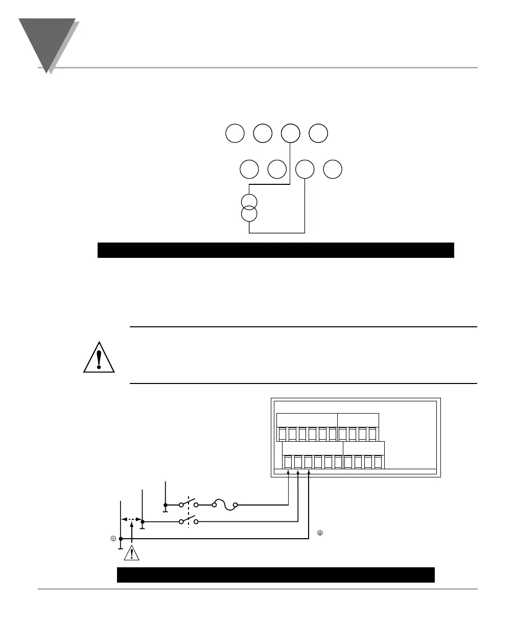
3.4 CONNECTING SENSOR INPUTS (Continued)
Figure 3-12. DC Current Input Connections with Current Source
3.5 CONNECTING MAIN POWER
Connect the AC main power connections as shown in Figure 3-13.
WARNING: Do not connect AC power to your device until you have
completed all input and output connections. This device must only be
installed by a specially trained electrician with corresponding qualifications.
Failure to follow all instructions and warnings may result in injury!
Figure 3-13. Main Power Connections - AC Powered Unit
TB1 TB2
1234 123456
78910 567811 12
FUSE
EARTH GROUND
GREEN WIRE
AC Power
Check for proper Earth grounding in the power
distribution system (single phase).
SWITCH
LINE
NEUTRAL
EARTH
(L) LINE
(N) NEUTRAL
TB2
1234
5678
(+)
(-)
-E +E +20mA N/C
+24V +S -SN/C
MAX. 20mA
Artisan Technology Group - Quality Instrumentation ... Guaranteed | (888) 88-SOURCE | www.artisantg.com

Table of Contents

Other manuals for Omega DP25B-E

Questions and Answers:

Question and Answer IconNeed help?

Do you have a question about the Omega DP25B-E and is the answer not in the manual?

Omega DP25B-E Specifications

General IconGeneral
BrandOmega
ModelDP25B-E
CategoryMeasuring Instruments
LanguageEnglish

Related product manuals