19
Getting Started
3
3.5 CONNECTING MAIN POWER (Continued)
Table 3-2 shows the wire color and respective terminal connections for both USA and
Europe.
Table 3-2. Main Power Connection - AC Powered Unit
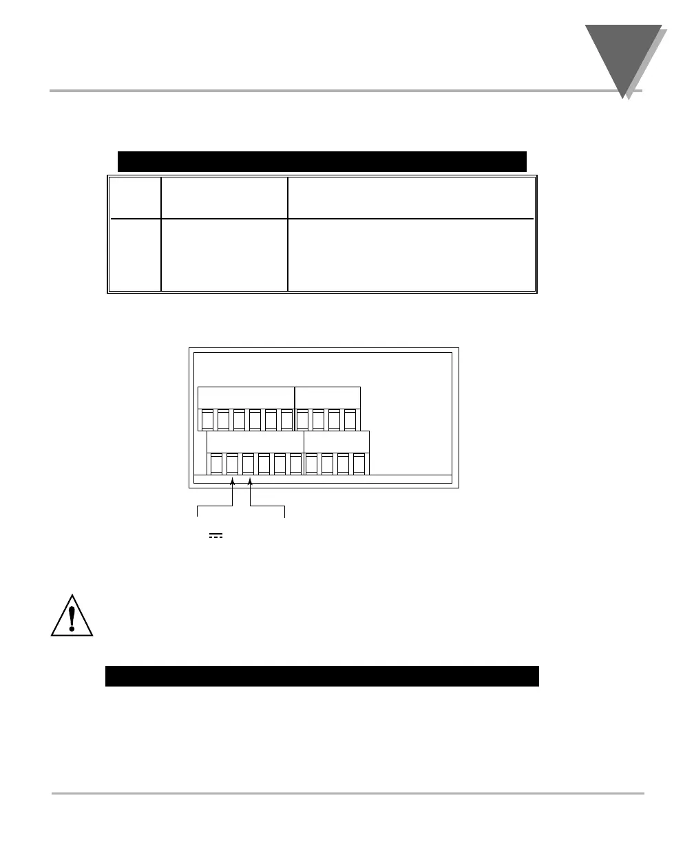
Connect the DC main power connections as shown in Figure 3-14.
When using DC power, refer to the Table 8-1 Color Chart in the Specifications
Section for Display Color, Intensity, Excitation Voltage and Current, and
Analog Output Isolated Option. Failure to use proper ratings may result in
damaging the unit.
Figure 3-14. Main Power Connections - DC Powered Unit
Artisan Technology Group - Quality Instrumentation ... Guaranteed | (888) 88-SOURCE | www.artisantg.com