Pin No. Code Description
1 N(-) Neutral Power / DC-Power supply
2 ALM2 C Alarm Relay 2 Common
3 ALM2 NO Alarm Relay 2 Normally Open
4 ALM2 NC Alarm Relay 2 Normally Closed
5 (+) DC + Power supply (9-36 VDC)
6 L Line Power (90-240 VAC)
7 ALM1 C Alarm Relay 1 Common
8 ALM1 NO Alarm Relay 1 Normally Open
9 ALM1 NC Alarm Relay 1 Normally Closed
Wiring Instructions
4
Section 4.2 - Connecting Power
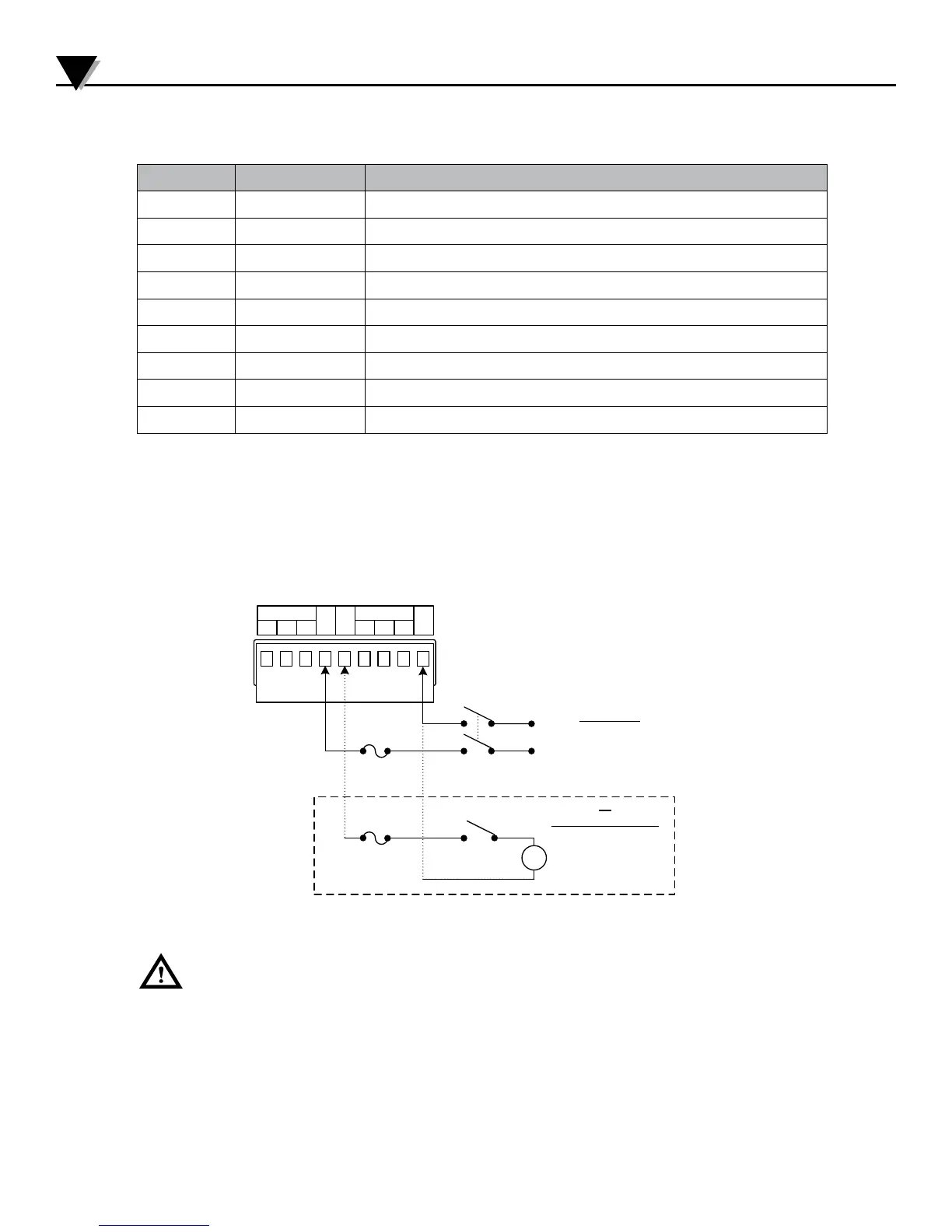
Table 2 - 9-Pin Input Power/Relay Wiring Summary
Connect the main power connections to pins 4 and 9 (AC Power) or pins 5 (+) and 9
(-) (DC Power) of the 9pin power / output connector as shown in Figure 3.
NC
L
ALM1
NO C
(+)
N(-)
NC
ALM2
NO C
19
N
L
SW
Fuse
SW
+
-
Or
DCPOWEROPTION
90–240Vac
9–36Vdc
ACPOWE R
Fuse
Figure 3 - Main Power Connections
For the low-voltage power option, maintain the same degree of protection as the
standard high-voltage input power units (90–240 Vac) by using a Safety Agency
Approved DC source with the same Overvoltage Category and pollution degree as
the AC model.
The Safety European Standard EN61010-1 for measurement, control, and laboratory
equipment requires that fuses must be specified based on IEC127. This standard
specifies the letter code “T” for a Time-lag fuse.
5

 Loading...


