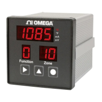
DP600A, DP606A, DP612A Series
Table of
Contents
Table of Figures and Tables
Figures ..................................................................................... Page
Figure 1 Side and Panel Cutout Views ...................................................... 3
Figure 2 DP606A/DP612A: Rear Panel Connections ............................... 4
Figure 3 Main Power Connections ............................................................. 5
Figure 4 Relay Connections ......................................................................... 6
Figure 5 3 Wire RTD Wiring Diagram ....................................................... 7
Figure 6 Front Panel Diagram ..................................................................... 8
Figure 7 Process Input Scaling .................................................................. 18
Table ........................................................................................ Page
Table 1 Rear Panel Connections ................................................................ 4
Table 2 9 Pin Input Power/Relay Wiring Summary .............................. 5
Table 3 Connecting Communications ...................................................... 7
Table 4 Function Codes ............................................................................. 10
Table 5 Device Configuration .................................................................. 14
Table 6 Alarm Relay Configuration ....................................................... 17
Table 7 Serial Port Configuration ........................................................... 19
Table 8 Modbus Functions ....................................................................... 20
Table 9 Mulitple Register Writes ............................................................ 22
Table 10 Packet Sizes ................................................................................... 22
Table 11 System Registers .......................................................................... 23
Table 12 Temperature Registers ................................................................ 24
Table 13 Sensor Status Registers ............................................................... 24
Table 14 Zone Registers .............................................................................. 25
Table 15 User Calibration ........................................................................... 26
Table 16 Input Accuracy ............................................................................. 30

 Loading...