2022.11.18 REV. MASS FLOW METER OPERATING MANUAL 15
Sensor Setup
MENU → SETUP → Sensor
Choosing Engineering Units
SETUP → Sensor → Engineering Units
Changing device engineering units alters both the display and the data frame. Choose the
parameter whose unit you want to change, and then select your desired engineering unit,
confirming the change on the last screen.
Defining STP/NTP Reference Values
SETUP → Sensor → STP Flow Ref or NTP Flow Ref
Standardized flow rates are reported in “standard” or “normal” volumetric flow units that
reference a given temperature and pressure combination. This reference is called STP
(standard temperature and pressure) or NTP (normal temperature and pressure). Depending
on the engineering units selected, either STP or NTP will be editable from this menu.
Reference options:
• Stan T: Standard Temperature
• Stan P: Standard Pressure
• Norm T: Normal Temperature
• Norm P: Normal Pressure
• Ref temp units changes the temperature units used for STP and NTP calculations.
• Ref pressure units changes the pressure units used for STP and NTP calculations
Unless otherwise requested, your flow meter ships with a default STP of 25°C and 1 atm
(which aects flow units beginning with “S”), and an NTP of 0°C and 1 atm (which aects
flow units beginning with “N”).
!
Warning: Changes to STP or NTP references will alter your mass flow readings.
Flow and Pressure Averaging
SETUP → Sensor → Flow Averaging
SETUP → Sensor → Pressure Averaging
Averaging the flow and pressure over a longer time may be useful in smoothing fluctuating
readings. This menu changes the time constants of the geometric running averages for
flow and pressure. Values roughly correspond to the time constant (in milliseconds) of the
averaged values. Higher numbers generate a greater smoothing eect, to a maximum of
255 ms.
Zero Band
SETUP → Sensor → Zero Band
The zero band threshold is an amount of flow under which flow values are displayed as .
The maximum zero band is 6.38%. This function also applies to gauge pressure readings
when using the optional barometer. For example, a 20 meter with a zero band value
of 0.25% would display all readings below 0.05 as .
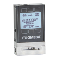
The sensor setup menu.
The engineering units menu
(page 11).
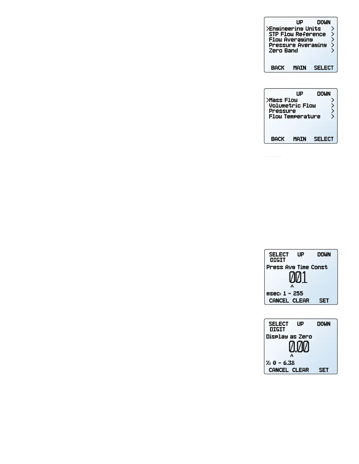
Adjusting the flow averaging time
constant.
Configuring the zero band.
 Loading...