2022.11.18 REV. MASS FLOW METER OPERATING MANUAL 27
Pinouts
Check the calibration data sheet and pinout for your device.
See page 18 for additional important information about connecting your device to a computer for serial commands.
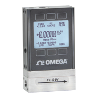
8-Pin Mini-DIN (Default)
Pin Function
Not Connected Optional: 4–20 mA primary output signal
Static 5.12 Vdc Optional: secondary analog output (4–20 mA, 0–5 Vdc, 1–5 Vdc, 0–10 Vdc) or basic alarm
Serial RS-232RX Input Signal Optional: RS-485 A
Remote tare (ground to tare)
Serial RS-232TX Output Signal Optional: RS-485 B
0–5 Vdc Analog Out Optional: 1–5 Vdc or 0–10 Vdc output signal
Power In
Ground (common for power, digital communications, analog signals, and alarms)
!
Warning: Do not connect power to pins 1 through 6, as permanent damage can occur. It is common to mistake pin 2 (labeled
5.12 Vdc Output) as the standard 0–5 Vdc analog output signal. Pin 2 is normally a constant 5.12 Vdc.
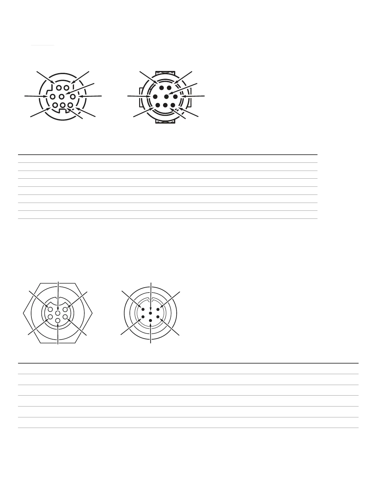
Locking Industrial Connector Pinout
Pin Function
Power In (+)
RS-232TX / RS-485 B
RS-232RX / RS-485 A
Remote tare (ground to tare)
Ground (common for power, communications, and signals)
Analog Out (voltage or current as ordered)
✓
Note: The availability of dierent output signals depend on the options ordered.
Male ConnectorFemale Connector
4
5
6
8
7
3
4
5
6
8
7
3
Male Connector
Female Connector
1
2
4
5
5
4
2
1
 Loading...