6 Getting Started
Getting Started
Getting to Know Your Mass Flow Meter
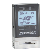
The Flow Meter Display
The figure to the right identifies the various features of the flow meter display.
Highlights pressure in the center of the device.
Highlights temperature in the center of the device.
Tares the device’s flow measurement (page 10).
Highlights volumetric (actual) flow rate in the center of the device.
Highlights mass flow rate in the center of the device (default).
MENU enters the main menu system.
NEXT accesses the optional flow totalizer (page 11).
Toggles the backlight.
Status Messages
Status messages are shown to the right of the main readout number. In the example to the
right the OVR message shows that the totalizer rolled over to zero.
ADC Analog-digital converter error
LCK Front display is locked
MOV Mass flow over range of device
OVR Totalizer rolled over to zero
POV Pressure over range of device
TMF Totalizer missed out-of-range flow
TOV Temperature over range of device
VOV Volumetric flow over range of device
Mounting
Flow meters do not require straight runs of pipe upstream or downstream. Most flow meter
models can be mounted in any position, including upside-down. Corrosive-resistant flow
meters use media-isolated sensors that must be tared after changing orientation.
Filters
When pressure drop is not a concern, use in-line sintered filters to prevent large particulates
from entering the flow body of the meter. Suggested maximum particulate sizes are as follows:
• 5 microns for units with flow ranges ≤1 .
• 20 microns for units with flow ranges between 1 and 1 .
• 50 microns for units with flow ranges ≥1 .
The main display. Note the button
behind the logo, which toggles the
device backlight.
The main display with barometer
(PSIG) and an OVR status
message.
 Loading...