8 Getting Started
Option: Charging Your Portable Meter
Portable meters’ batteries are partially charged before shipping. When fully charged,
typical battery life is 18 hours with a monochrome display, or 8 hours with a TFT color
display. Dimming the backlight will increase battery life. When the battery indicator
displays it is completely empty, about 15 minutes of battery life remain.
Charge the device using the supplied USB cable (micro-B to type A) or a similar cable.
Any USB outlet on a computer or portable power supply may be used, but charging will
be fastest (approximately 3.5 hours) when connected to the supplied 2.0 A power supply.
The red indicator LED on top of the device lights up to indicate that the unit is charging,
and turns o when the battery is charged.
Your meter may be used while it is charging. If the battery has been fully depleted, you may
need to charge the pressure gauge for a full minute before the device can be turned on.
!
Warning: The safe charging temperature range is 0–45°C (32–113°F). If internal
sensors detect temperatures outside of this range, the battery will not charge.
Power and Signal Connections
Power can be supplied to your meter through either the power jack or the multi-pin
connector on top of your device.
✓
Note: Power requirements vary based on analog configuration and valve type.
Please reference the associated specification sheet for power requirements.
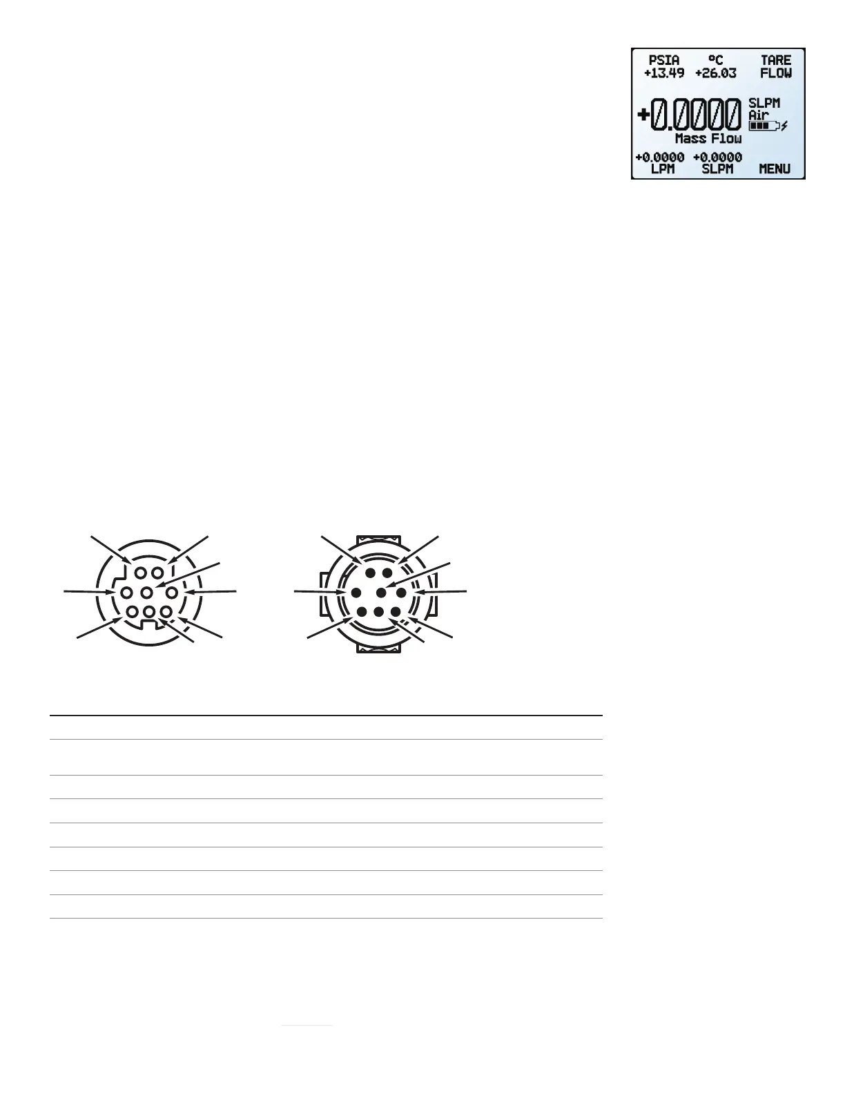
Standard 8-Pin Mini-DIN Pinout
Pin Function
Not Connected Optional: 4–20 mA primary output signal
Static 5.12 Vdc Optional: secondary analog output (4–20 mA,
0–5 Vdc, 1–5 Vdc, 0–10 Vdc) or basic alarm
Serial RS-232RX / RS-485(–) input signal (receive)
Remote tare (ground to tare)
Serial RS-232TX / RS-485(+) output signal (send)
0–5 Vdc Optional: 1–5 Vdc or 0–10 Vdc output signal
Power In (as described above)
Ground (common for power, digital communications, analog signals and alarms)
The above pinout is applicable to all devices with the Mini-DIN connector. The availability of dierent output
signals depends on the options ordered. Optional configurations are noted on the unit’s calibration sheet.
▲
Caution: Do not connect power to pins 1 through 6, as permanent damage can occur.
It is common to mistake pin 2 (labeled 5.12 Vdc Output) as the standard 0–5 Vdc
analog output signal. Pin 2 is normally a constant 5.12 Vdc.
For more pinout configurations, see page 27.
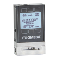
The main display with battery
information and an active charging
indicator (the lightning bolt).
Male ConnectorFemale Connector
4
5
6
8
7
3
4
5
6
8
7
3
 Loading...