Conditions of conformity of EU directives
38
b) According to EN61800-3 it is mandatory to mention that any inverter with only C3 filter inside
may NOT be connected to a low voltage public power supply in residential areas since for these
installations C1 is required.
c) In case of external filter for C2, an additional note is required according to EN61800-3 that “this
product may emit high frequency interference in residential areas which may require additional
EMC measures”.
d) According to the EN6100-3-12, an additional AC reactor or DC choke should be installed for
reducing harmonics in power line.
3. Wiring requirements
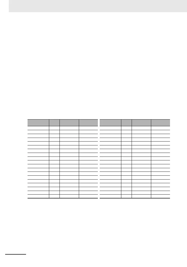
a) A shielded wire (screened cable) must be used for motor wiring, and the length of the cable must
be according to the following table.
b) The carrier frequency must be set according to the following table to meet an EMC requirement.
c) The main circuit wiring must be separated from the control circuit wiring.
4. Environmental requirements (to be met when a filter is used)
a) 3G3RX2 series inverter that is activated built-in EMC filter must be according to 3G3RX2 series
specifications.
Table 1
■Conditions of Electrical Safety (LVD)
The condition in the next section UL standard explain the condition of the electrical safety. It is neces-
sary to comply with the description items such as temperature condition, installation condition etc.
Model
3G3RX2
Cat. Cable length
Carrier
frequency
Model
3G3RX2
Cat. Cable length
Carrier
frequency
A2004 C3 10m 2kHz -- -- -- --
A2007 C3 10m 2kHz A4007 C3 10m 2kHz
A2015 C3 10m 2kHz A4015 C3 10m 2kHz
A2022 C3 10m 2kHz A4022 C3 10m 2kHz
A2037 C3 10m 2kHz A4037 C3 10m 2kHz
A2055 C3 5m 2kHz A4055 C3 5m 2kHz
A2075 C3 5m 2kHz A4075 C3 5m 2kHz
A2110 C3 5m 2kHz A4110 C3 5m 2kHz
A2150 C3 10m 1kHz A4150 C3 10m 2kHz
A2185 C3 10m 1kHz A4185 C3 10m 2kHz
A2220 C3 10m 1kHz A4220 C3 10m 2kHz
A2300 C3 5m 2kHz A4300 C3 5m 2kHz
A2370 C3 5m 2kHz A4370 C3 5m 2kHz
A2450 C3 5m 2kHz A4450 C3 5m 2kHz
A2550 C3 5m 2kHz A4550 C3 5m 2kHz
--- --- --- --- B4750 C3 3m 2kHz
--- --- --- --- B4900 C3 3m 2kHz
--- --- --- --- B411K C3 3m 2kHz
--- --- --- --- B413K C3 3m 2kHz
 Loading...


