37
Conditions of conformity of EU directives
Conditions of conformity of EU directives
■Specifications
• This is a product designed for industrial environments.
Use in residential area may cause radio interference, in which case the user may be required to take
adequate measures to reduce interferense.
• This type of PDS is not intended to be used on a low-voltage public network which supplies domestic
premises.
■Manufacturer and EU Representative
Manufacturer: OMRON Corporation
Shiokoji Horikawa, Shimogyo-ku, Kyoto, 600-8530 Japan
Representative and Importer in EU: OMRON EUROPE B.V.
Wegalaan 67-69,2132 JD Hoofddorp, The Netherlands
GENERAL:
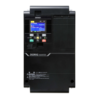
3G3RX2 series Type inverter is open type AC Inverter with three phase input and three phase output. It
is intended to be used in an enclosure. It is used to provide both an adjustable voltage and adjustable
frequency to the ac motor. The inverter automatically maintains the required volts-Hz ratio allowing the
capability through the motor speed range. It is multi-rated device and the ratings are selectable accord-
ing to load types by operator with key pad operation.
■Compatibility Conditions of EMC Directives
CAUTION for EMC
(Electromagnetic Compatibility)
3G3RX2 series inverter conforms to requirements of Electromagnetic Compatibility (EMC) Directive
(2014/30/EU). However, when using the inverter in Europe, you must comply with the following specifi-
cations and requirements to meet the EMC Directive and other standards in Europe:
1. Power supply requirements
a) Voltage fluctuation must be -15% to +10% or less.
b) Voltage imbalance must be ±3% or less.
c) Frequency variation must be ±4% or less.
d) Total harmonic distortion (THD) of voltage must be±10% or less.
2. Installation requirement
a) 3G3RX2 series includes a built-in EMC filter. The built-in EMC filter must be activated.
EMC EN61800-3:2004/AI:2012
Machinery IEC61800-5-2:2016
EN ISO 13849-1:2014
EN61800-5-1:2007
This equipment must be installed, adjusted, and maintained by qualified engineers who have
expert knowledge of electric work, inverter operation, and the hazard ouscircumstances that
can occur. Otherwise, personal injury may result.

 Loading...


