5 DriveProgramming User Variables
5 - 18
DriveProgramming User’s Manual (I622-E1)
5-6 Input Variables
You can execute the functions allocated to the input terminals by the DriveProgramming program. The
following variables correspond to the functions which can be allocated to the input terminals.
If any of the variables is set to 1 (ON), the corresponding function is enabled in the same way as when
the input terminal is turned ON.
If any of the variables is set to 0 (OFF), the corresponding function is disabled. You can execute the
functions by the program even if you do not allocate the functions to the Input Terminal Selection
(CA-01 to CA-01). The Reference column in the following table shows the function setting data for the
inverter. For details on each function, refer to the High-function General-purpose Inverter 3G3RX2
Series User's Manual (I620).
Example
If you set FW (forward) to 1, the forward RUN command is executed.
FW: = 1 the inverter starts forward operation.
FW: = 0 the inverter stops forward operation and starts deceleration.
Precautions for Correct Use
• If the DriveProgramming program is stopped, the data of the input variables is not retained
but cleared to zero.
• The variable FW (forward) and RV (reverse) are enabled only when the inverter's RUN Com-
mand Selection (AA111) is set to 00 (FW/RV terminal). The inverter does not operate with
other setting options.
• Even if you set the variable FW (forward) or RV (reverse) to 1 immediately after turning on
the power supply, the setting is ignored and neither forward or reverse operation is per-
formed. Set 0, and then set 1 again. To avoid this operation, create a program that has one
second of wait time after turning on the power supply, with such as “wait” command.
• The relationship between the inverter's input terminal function set in the Input Terminal
Selection and the input variable is logical OR.
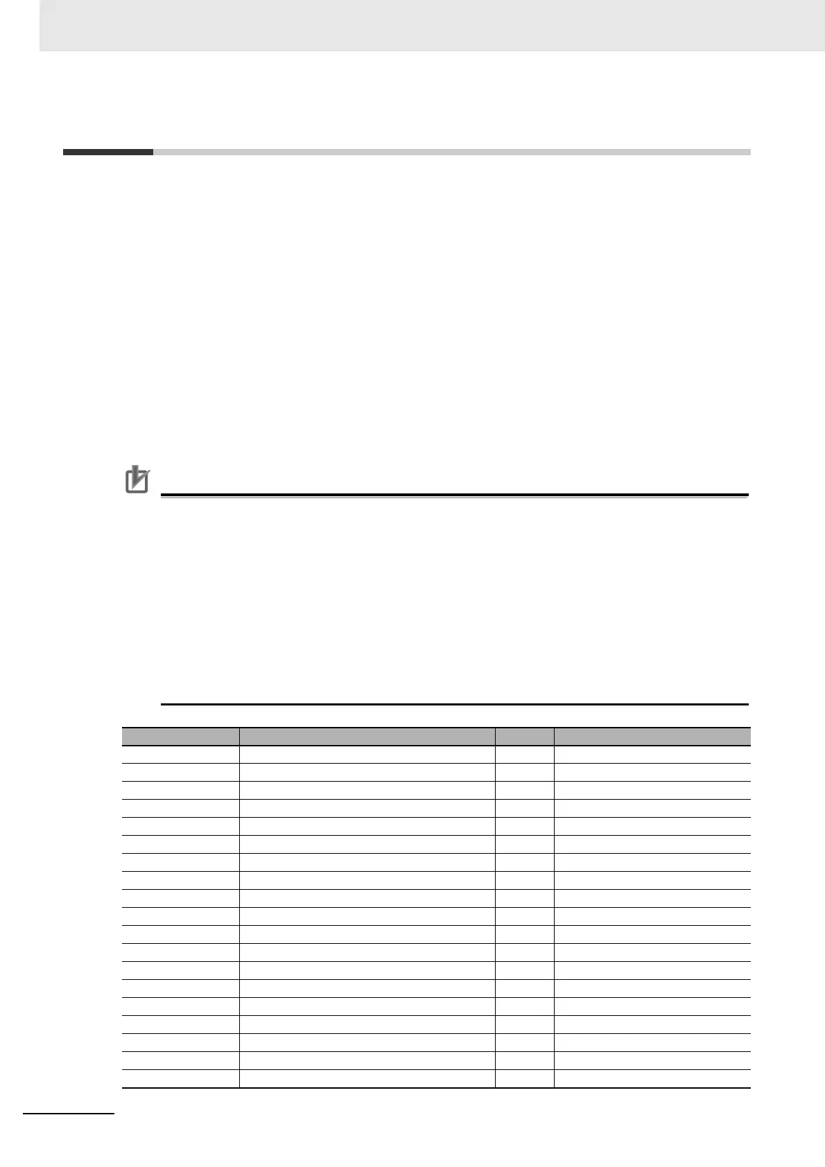
Function variable Description R/W Reference
no Without allocation R/W CA-01 to CA-11 = 0
FW Normal rotation R/W CA-01 to CA-11 = 1
RV Reverse rotation R/W CA-01 to CA-11 = 2
CF1 Multistage speed 1 R/W CA-01 to CA-11 = 3
CF2 Multistage speed 2 R/W CA-01 to CA-11 = 4
CF3 Multistage speed 3 R/W CA-01 to CA-11 = 5
CF4 Multistage speed 4 R/W CA-01 to CA-11 = 6
SF1 to SF7 Multistage speed bit 1 to 7 R/W CA-01 to CA-11 = 7 to 13
ADD Addition of frequency R/W CA-01 to CA-11 = 14
SCHG Switching of command R/W CA-01 to CA-11 = 15
STA 3-wire starting up R/W CA-01 to CA-11 = 16
STP 3-wire stopping R/W CA-01 to CA-11 = 17
F/R 3-wire normal and reverse R/W CA-01 to CA-11 = 18
AHD Retention of analog command R/W CA-01 to CA-11 = 19
FUP Acceleration through remote operation R/W CA-01 to CA-11 = 20
FDN Deceleration through remote operation R/W CA-01 to CA-11 = 21
UDC Clearing of remote operation data R/W CA-01 to CA-11 = 22
F-OP Forced switching of command R/W CA-01 to CA-11 = 23
SET Second control R/W CA-01 to CA-11 = 24
 Loading...


