Product Specifications
Motion Control Unit
11
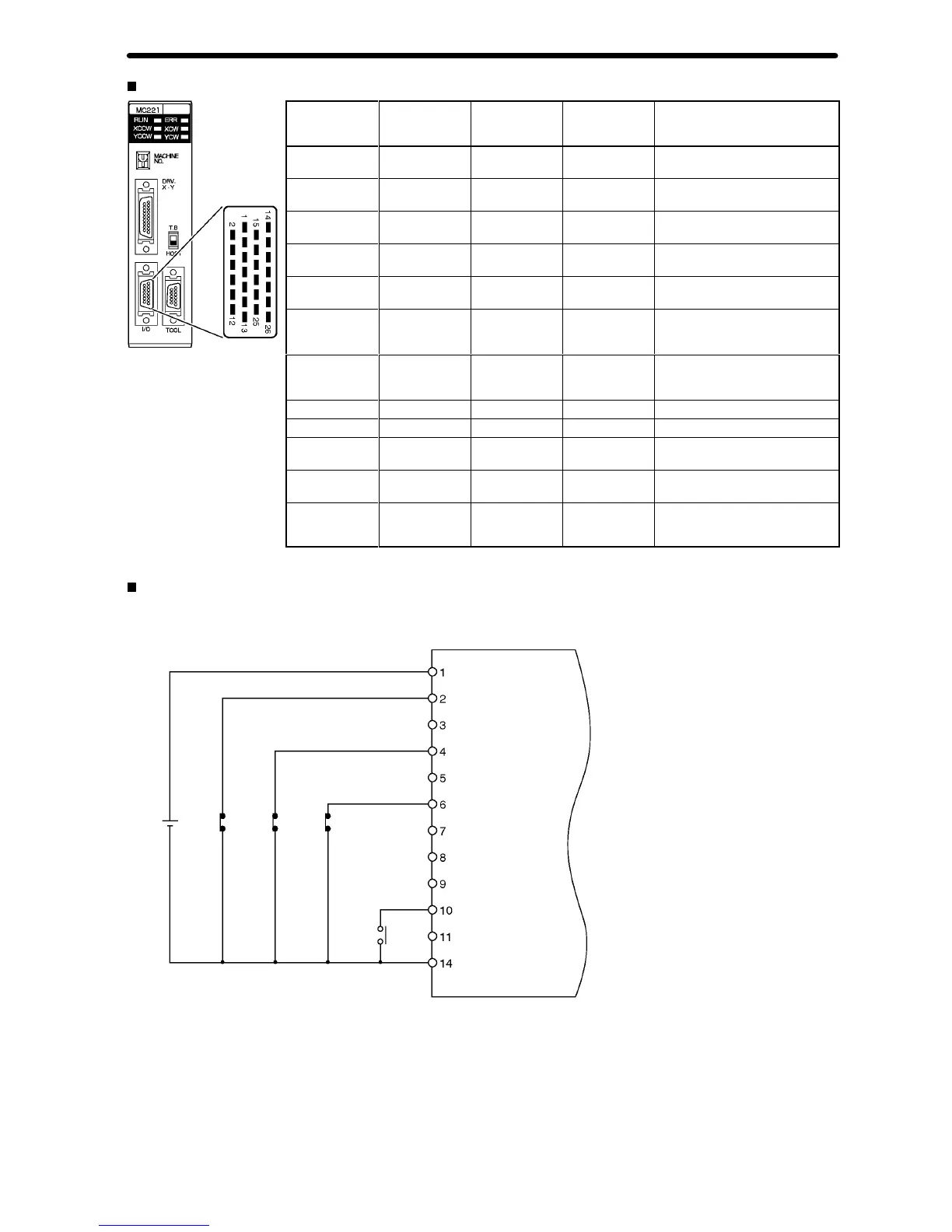
External I/O Connections: Input Connector
Pin Symbol Terminal
on
MC Unit
terminal block
Name Function
1
+24 V
10
24-VDC input
Connects to the + terminal of the
24-VDC external power supply
.
2 XCWL (NC) 11 X-axis CW limit
input
Limits movement of the X axis in
the CW direction.
3 YCWL (NC) 16 Y
-axis CW limit
input
Limits movement of the Y axis in
the CW direction.
4 XCCWL (NC) 12 X-axis CCW
limit input
Limits movement of the X axis in
the CCW direction.
5 YCCWL (NC) 17 Y-axis CCW
limit input
Limits movement of the Y axis in
the CCW direction.
6 XSTOP (NC) 14 X-axis
emergency
stop input
Disables the X-axis run output
and stops it.
7 YSTOP (NC) 8 Y-axis
emergency
stop input
Disables the Y
-axis run output
and stops it.
8 IN1 (NO) 4
General input 1 General input 1
9 IN2 (NO) 9
General input 2 General input 2
10 XORG (NC,
NO)
13
X-axis origin
proximity input
Used for the X-axis origin search.
11 YORG (NC,
NO)
18 Y
-axis origin
proximity input
Used for the Y
-axis origin search.
14 DC GND 0
24-VDC input
ground
Connects to the – terminal (0 V)
of the 24-VDC external power
supply.
“NC” stands for normally closed and “NO” stands for normally open.
External Connection Diagram
Using the MC Unit Input Connector
Emergency
stop input
CCW
limit
input
CW
limit input
24 VDC
Origin
proximit
y input
Input Connector
Pin No.
24-VDC input
X-axis CW limit input
Y-axis CW limit input
X-axis CCW limit input
Y-axis CCW limit input
X-axis emergency stop input
Y-axis emergency stop input
General input 1
General input 2
X-axis origin proximity input
Y-axis origin proximity input
24-VDC input ground
Example:
X-axis W
iring
Connector:
Wire and assemble the connector by using
the connector case provided with the Unit
or by using the XW2Z-100J-F1 MC Unit
T
erminal Block Connecting Cable.
+
–
 Loading...


