E5jJ
E5jJ
Precautions
Mounting
The dimensions of the Temperature Controller conform to
DIN 43700.
Recommended panel thickness is 1 to 8 mm for the
E5AJ,
E5BJ, and E5EJ, and 1 to 4 mm for the E5CJ.
The mounted T
emperature Controller must be horizontally level.
Do not install the Temperature Controller in a location exposed to
excessive
dust or corrosive gases. Moreover
, avoid locations sub
-
ject
to heavy vibration or shock, water or oil spray, or high tempera
-
tures.
Any of these conditions will af
fect product life.
Isolate the T
emperature Controller from equipment that generates
strong,
high-frequency noises such as high-frequency welders, be
-
cause
such equipment may prevent proper operation.
E5AJ/E5BJ/E5EJ
Two
mounting brackets are provided with the T
emperature Control
-
ler.
Mount one of the brackets to the top and the other one to the bot
-
tom
of the T
emperature Controller
. T
urn the ratchets of the mounting
brackets
clockwise with a Phillips screwdriver until they snap.
Insert
the unit back into the case by pushing the unit until it clicks into
place.
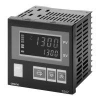
E5CJ
Insert
the T
emperature Controller into the square hole of the panel
and insert an adapter from the backside so that there will be no
space
between the T
emperature Controller and the
panel. Then se
-
cure
the T
emperature Controller with a screw
.
Tightening screw
Dismounting
Loosen
the screw of the adapter for dismounting.
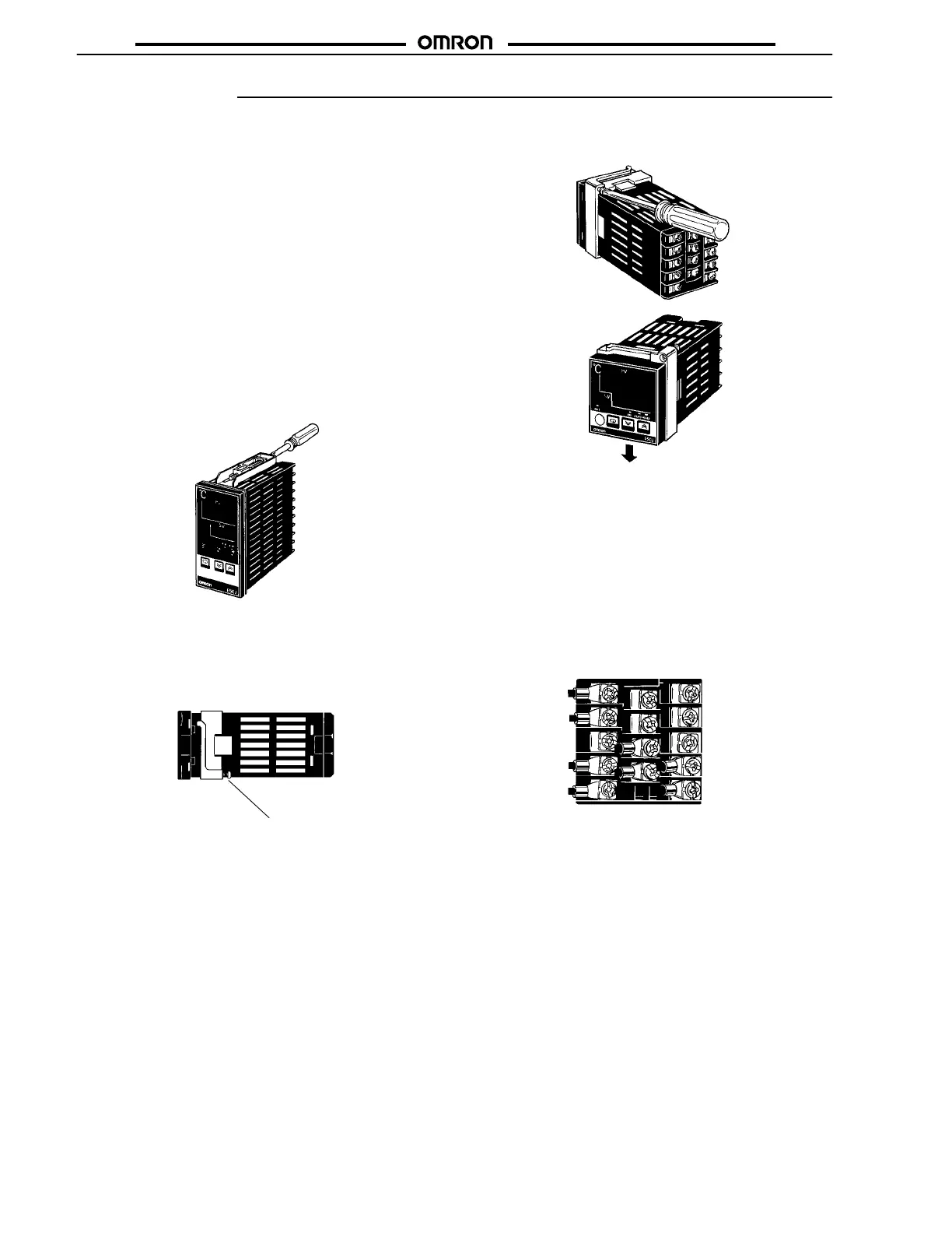
Connection Example
With
Solderless T
erminal
Use
M3.5 x 8 solderless terminals with
the T
emperature Controller
’s
M3.5 self-rising pressure plate screws.
Solder-dipped Leads
Strip
6 to 8 mm of the lead wires and carefully arrange the wire tips.
Do
not tighten the terminal screw with excessive force, because do
-
ing
so many damage them. The terminal block
of the T
emperature
Controller
is constructed so that the lead wires can be connected to
all
the terminals from the same direction.
Example: E5CJ
Input Type Connection
To
reduce inductive noise influence, the lead wires connecting the
input
type
to the T
emperature Controller must be separated from the
power
lines and load lines.
Use the specified compensating conductors for thermocouples.
Use lead wires having a small resistance for platinum resistance
thermometers.
Sequenced Circuits
Several
seconds are required until the relay is turned ON after pow
-
er
has been supplied to the T
emperature Controller
. Therefore, take
this time delay into consideration when designing sequenced cir-
cuits
which incorporate a T
emperature Controller
.
 Loading...