E5jJ
E5jJ
8
Input type selector
(INPUT)
Alarm mode selector 2
(ALM2)
Alarm mode selector 1
(ALM1)
Function selector
(FUNCTION)
Key protection switch
(PROTECT)
E5BJ
Top
V
iew
Bottom View
Alarm mode selector 2
(ALM2)
Key protection switch
(PROTECT)
Alarm mode selector 1
(ALM1)
Input type selector
(INPUT)
Function selector
(FUNCTION)
E5EJ
Top
V
iew
Bottom View
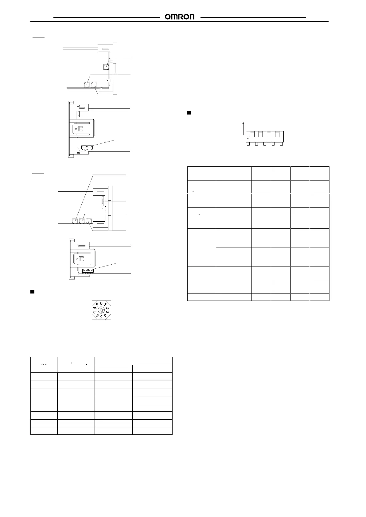
Input Type Selector (INPUT)
This
selector selects the temperature sensor to be used. It is facto
-
ry-set
to position 2 to designate a K-type (chromel-alumel thermo
-
couple)
temperature sensor
. The following table lists the other pos
-
sible
settings for temperature sensors. Refer to temperature
range
charts
under
Ordering Information
for further information.
Switch
Temperature
T
emperature range
setting
sensor code
°C °F
0, 8
JPt100 –199.9to650.0 –199.9 to 999.9
1, 9
Pt100 –199.9to650.0 –199.9 to 999.9
2 K –200 to1,300 –300 to 2,300
3 J –100 to 850 –100 to 1,500
4 T –199.9to400.0 –199.9 to 700.0
5 L –100 to 850 –100 to 1500
6 U –199.9to400.0 –199.9 to 700.0
7 N –200 to1,300 –300 to 2,300
Note: JPt100:
139.16
Ω
at 100
°C
Pt100:
138.50
Ω
at 100
°C
Temperature Control in Fahrenheit
1. After setting all internal switch settings, set pin number 4 of
the
function switch to ON. This pin is normally set to OFF
.
2. Insert
the internal mechanism into the housing and turn on
the
Temperature
Controller
.
3. du will be displayed. Then press the Up Key to change the
set value display into Fahrenheit “
f.”
4. Turn
of
f the power 2 s after the set value display has changed
to
Fahrenheit.
5. Remove the internal mechanism from the housing, set pin
number
4 of the function switch to OFF
, replace it and turn on
the
power
.
Function Selector (FUNCTION)
1234
O
N
ON
OFF
The
DIP switch sets the operating parameters listed in the
following
table.
All pins are factory-set to OFF
.
Function selector pin
number
1 2 3 4
Output
operation
Normal
(see note 1)
ON --- --- ---
Reverse (see
note 1)
OFF --- --- ---
Control
ON/OFF --- ON --- ---
mode
Advanced
PID
--- OFF --- ---
PID
tuning
mode
With
auto-tuning
(see note 2)
--- --- ON
(see
note
3)
---
With fuzzy
self-tuning
--- --- OFF
(see
note
3)
---
Level
Engineering
level
--- --- --- ON
Normal
operation
--- --- --- OFF
Factory
setting
OFF OFF OFF OFF
Note: 1. For heating applications, use the reverse operation
mode. For cooling applications use the normal opera-
tion
mode. (In other cases, select the desired setting.)
2. To start auto-tuning, press the Level and Display Keys
simultaneously, for 1 s or longer to start auto-tuning.
During auto-tuning, the set value display flashes. (The
display
will stop flashing after tuning is finished.)
3. If the control mode is ON/OFF, pin 3 can be set ON or
OFF.
(Pin 3 is not important
in case of ON/OFF control.)
 Loading...