E5jJ
E5jJ
9
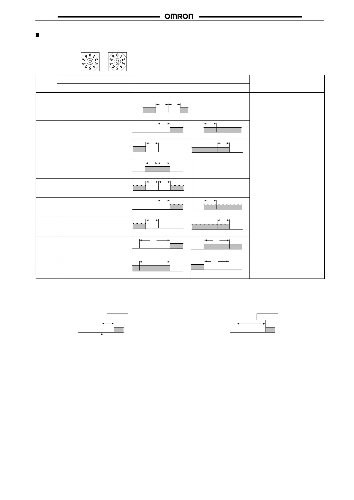
Alarm Mode Selectors (ALM1, ALM2)
Alarm
modes, listed
in the following table, can be selected using this switch. The switch is factory-set to position 2, i.e., the upper-limit alarm
mode.
Switch Mode Alarm output
Setting range
setting
Alarm operation
When X is positive
When X is negative
0
No alarm
OFF ---
1 Upper- and lower-limit alarm
(deviation)
XX
ON
OFF
SP
Always ON –1999
to 9999, or –199.9 to 999.9
(The decimal position varies with
the
input type.)
2
Upper-limit alarm (deviation)
X
SP
X
SP
3
Lower-limit alarm (deviation)
X
SP
X
SP
4 Upper- and lower-limit alarm
(deviation)
XX
SP
Always OFF
5 Upper- and lower-limit alarm with
standby
sequence (deviation)
XX
SP
Always OFF
6
Upper-limit alarm with standby
sequence (deviation)
X
SP
X
SP
7
Lower-limit alarm with standby
sequence (deviation)
X
SP
X
SP
8
Absolute-value upper-limit alarm
0°C/°F
X
0°C/°F
X
9
Absolute-value lower-limit alarm
0°C/°F
X
0°C/°F
X
Deviation Alarm
If
the alarm mode selector is set to a number between 1 to 7, alarm
values
are set to the width deviated from the set point as shown in
the
following illustration.
Set point (SP)
100°C/°F
Alarm value
10°C/°F
110°C/°F
Absolute Alarm
If
the alarm mode selector is set to 8 or 9, alarm values are set to the
absolute
value based on 0
°C/°
F as shown in the following illustra
-
tion.
0°C/°F
Alarm value
110°C/°F
110°C/°F
 Loading...