5 Communications Data for Modbus
5 - 4
E5C-T Digital Temperature Controllers Programmable Type Communications Manual (H186)
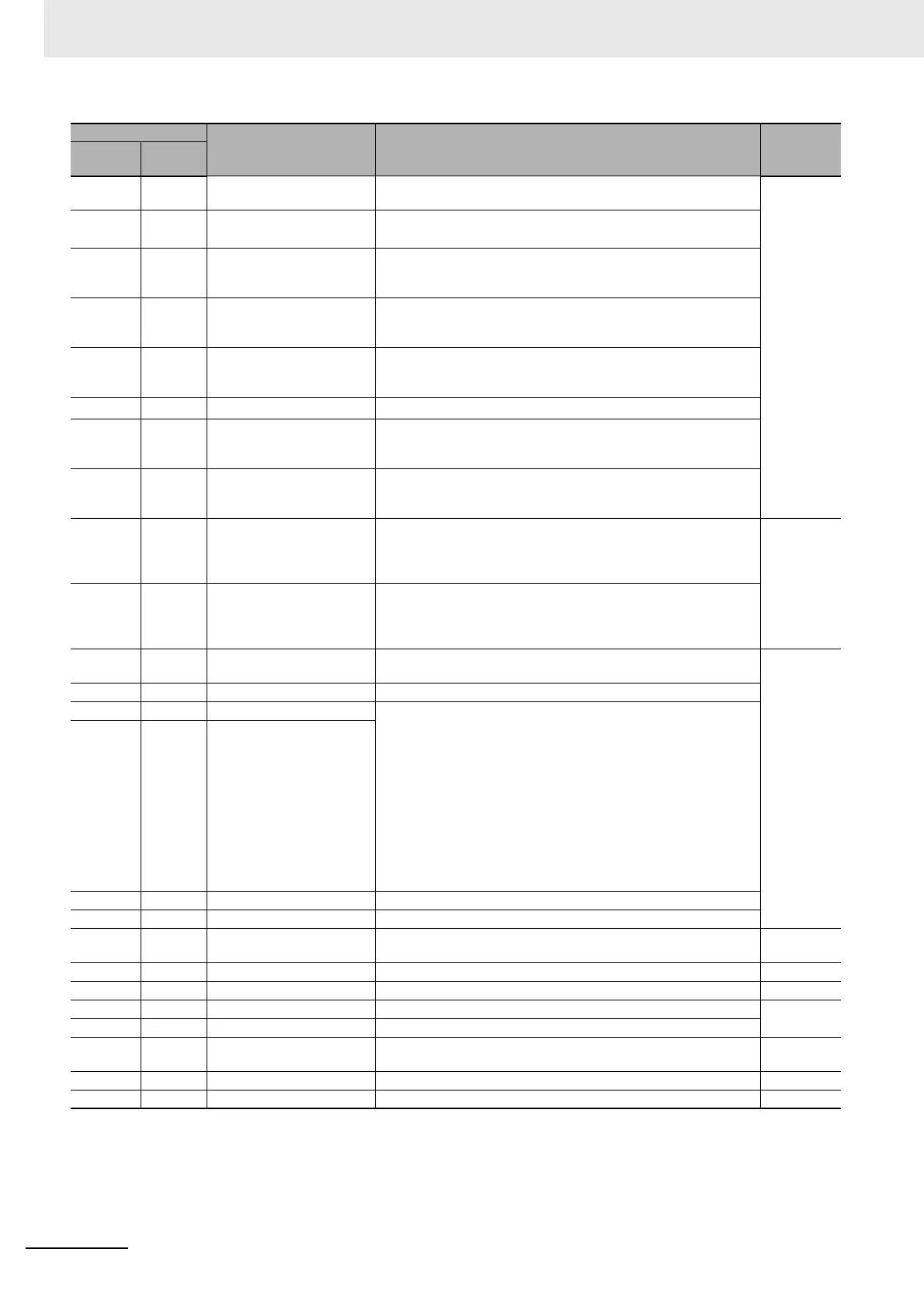
0620 2610 SP Mode Setting Monitor
(SP Mode)
H'00000000 (0): Program SP mode
H'00000001 (1): Fixed SP mode
Adjustment
0702 2701 Proportional Band
(Cooling)
*1
H'00000001 to H'0000270F (0.1 to 999.9)
0704 2702
Integral Time (Cooling)
*1
H'00000000 to H'0000270F
(0 to 9999: Integral/derivative time unit is 1 s.)
(0.0 to 999.9: Integral/derivative time unit is 0.1 s.)
0706 2703
Derivative Time (Cooling)
*1
H'00000000 to H'0000270F
(0 to 9999: Integral/derivative time unit is 1 s.)
(0.0 to 999.9: Integral/derivative time unit is 0.1 s.)
0708 2704
Dead Band
*1
H'FFFFF831 to H'0000270F
(−199.9 to 999.9 for temperature input)
(−19.99 to 99.99 for analog input)
070A 2705
Manual Reset Value
*1
H'00000000 to H'000003E8 (0.0 to 100.0)
070C 2706 Hysteresis (Heating) H'00000001 to H'0000270F
(0.1 to 999.9 for temperature input)
(0.01 to 99.99 for analog input)
070E 2707 Hysteresis (Cooling) H'00000001 to H'0000270F
(0.1 to 999.9 for temperature input)
(0.01 to 99.99 for analog input)
0710 2708 Control Period (Heating) H'FFFFFFFE (−2): 0.1 s
H'FFFFFFFF (−1): 0.2 s
H'00000000 (0): 0.5 s
H'00000001 to H'00000063 (1 to 99)
Initial
setting
0712 2709 Control Period (Cooling) H'FFFFFFFE (−2): 0.1 s
H'FFFFFFFF (−1): 0.2 s
H'00000000 (0): 0.5 s
H'00000001 to H'00000063 (1 to 99)
0714 270A Position Proportional Dead
Band
H'00000001 to H'00000064 (0.1 to 10.0) Adjustment
0716 270B Open/Close Hysteresis H'00000001 to H'000000C8 (0.1 to 20.0)
071E 270F MV at Reset Standard Models
Standard control:
H'FFFFFFCE to H'0000041A (−5.0 to 105.0)
Heating and cooling control:
H'FFFFFBE6 to H'0000041A (−105.0 to 105.0)
Position-proportional Models
Close position-proportional control with the Direct Setting of
Position Proportional MV parameter set to ON:
H'FFFFFFCE to H'0000041A (−5.0 to 105.0)
Floating position-proportional control or the Direct Setting of
Position Proportional MV parameter set to OFF:
H'FFFFFFFF to H'00000001 (−1 to 1)
0722 2711 MV at PV Error
0726 2713 MV Change Rate Limit H'00000000 to H'000003E8 (0.0 to 100.0)
0730 2718 PV Slope Coefficient H'00000001 to H'0000270F (0.001 to 9.999)
0734 271A Heater Current 1 Value
Monitor
H'00000000 to H'00000226 (0.0 to 55.0) Operation
0736 271B Heater Burnout Detection 1 H'00000000 to H'000001F4 (0.0 to 50.0) Adjustment
0738 271C Leakage Current 1 Monitor H'00000000 to H'00000226 (0.0 to 55.0) Operation
073A 271D HS Alarm 1 H'00000000 to H'000001F4 (0.0 to 50.0) Adjustment
0746 2723 Process Value Input Shift H'FFFFF831 to H'0000270F (−1999 to 9999)
0748 2724 Heater Current 2 Value
Monitor
H'00000000 to H'00000226 (0.0 to 55.0) Operation
074A 2725 Heater Burnout Detection 2 H'00000000 to H'000001F4 (0.0 to 50.0) Adjustment
074C 2726 Leakage Current 2 Monitor H'00000000 to H'00000226 (0.0 to 55.0) Operation
*1 The parameter for the currently selected PID set will be accessed. For setup area 1, however, the currently selected
PID set is fixed at PID1.
Address
Parameter name Setting (monitor) value Level
Four-byte
mode
Two-byte
mode