5 - 5
5 Communications Data for Modbus
E5C-T Digital Temperature Controllers Programmable Type Communications Manual (H186)
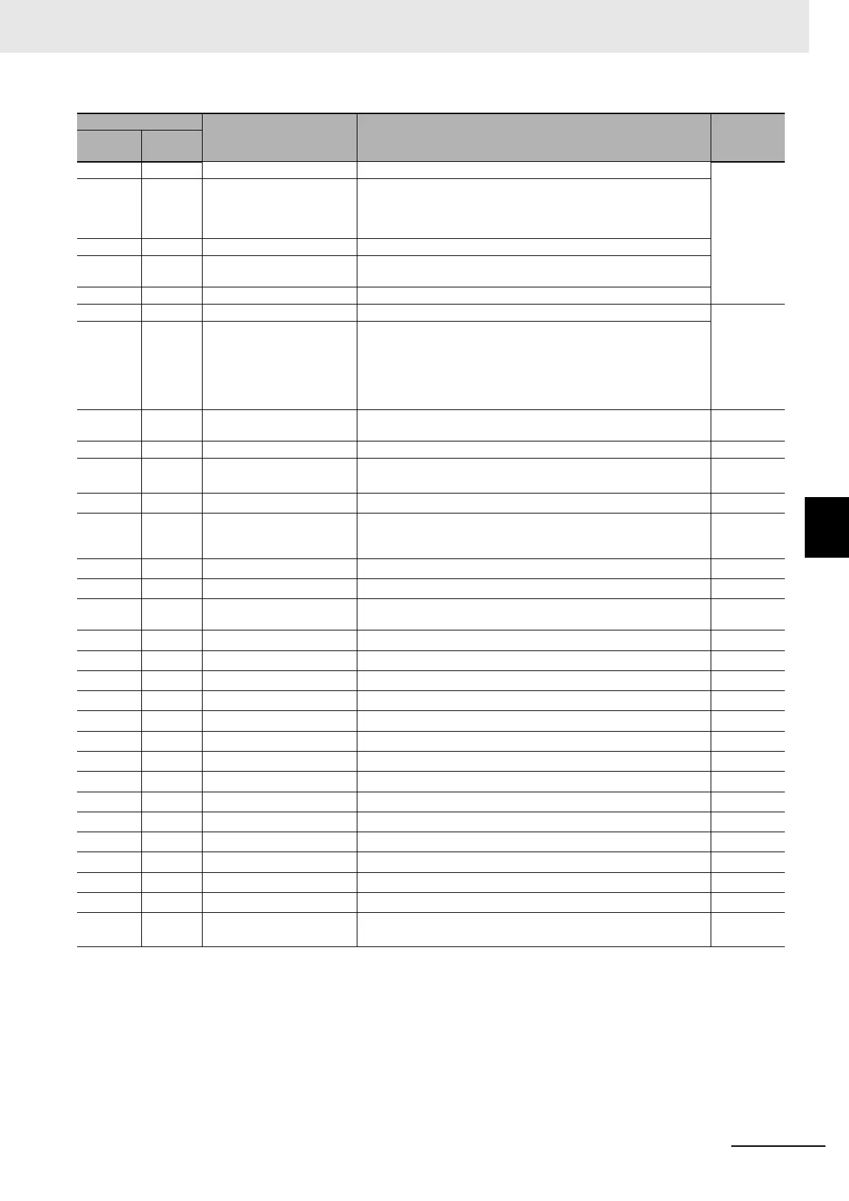
5-1 Variable Area (Setting Range) List
5
074E 2727 HS Alarm 2 H'00000000 to H'000001F4 (0.0 to 50.0) Adjustment
0754 272A Wait Band H'00000000 (0): OFF
H'00000001 to H'0000270F
(0.1 to 999.9 for Temperature input)
(0.01 to 99.99 for Analog input)
075A 272D Fixed SP SP lower limit to SP upper limit
075C 272E Standby Time H'00000000 to H'00009959 (hours, minutes)
H'00000000 to H'00009923 (days, hours)
075E 272F Program SP Shift Value H'FFFFF831 to H'0000270F (−1999 to 9999)
0800 2800 Input Digital Filter H'00000000 to H'0000270F (0.0 to 999.9) Advanced
function
setting
0808 2804 Moving Average Count H'00000000 (0): OFF
H'00000001 (1): 2 times
H'00000002 (2): 4 times
H'00000003 (3): 8 times
H'00000004 (4): 16 times
H'00000005 (5): 32 times
0810 2808 Extraction of Square Root
Low-cut Point
H'00000000 to H'000003E8 (0.0 to 100.0) Adjustment
1800 3800 Program Selection H'00000000 to H'00000007 (0 to 7) Program
1802 3801 Number of Segments
Used
*1
H'00000001 to H'00000020 (32)
1804 3802
Segment Selection
*1
H'00000000 to H'0000001F (31)
1806 3803
Segment Format
*2
H'00000000 (0): Ramp
H'00000001 (1): Soak
H'00000002 (2): Step
1808 3804
Segment SP
*2
SP Lower Limit to SP Upper Limit
180A 3805
Segment Slope
*2
H'00000000 to H'0000270F (0 to 9999)
180C 3806
Segment Time
*2
H'00000000 to H'00009959 (0.00 to 99.59) (hours, minutes)
H'00000000 to H'00009959 (0.00 to 99.59) (minutes, seconds)
180E 3807
PID Set No.
*1
H'00000000 to H'00000008 (0 to 8), (0): Automatic selection
1810 3808
Alarm Value 1
*1
H'FFFFF831 to H'0000270F (−1999 to 9999)
1812 3809
Alarm Value Upper Limit 1
*1
H'FFFFF831 to H'0000270F (−1999 to 9999)
1814 380A
Alarm Value Lower Limit 1
*1
H'FFFFF831 to H'0000270F (−1999 to 9999)
1816 380B
Alarm Value 2
*1
H'FFFFF831 to H'0000270F (−1999 to 9999)
1818 380C
Alarm Value Upper Limit 2
*1
H'FFFFF831 to H'0000270F (−1999 to 9999)
181A 380D
Alarm Value Lower Limit 2
*1
H'FFFFF831 to H'0000270F (−1999 to 9999)
181C 380E
Alarm Value 3
*1
H'FFFFF831 to H'0000270F (−1999 to 9999)
181E 380F
Alarm Value Upper Limit 3
*1
H'FFFFF831 to H'0000270F (−1999 to 9999)
1820 3810
Alarm Value Lower Limit 3
*1
H'FFFFF831 to H'0000270F (−1999 to 9999)
1822 3811
Alarm Value 4
*1
H'FFFFF831 to H'0000270F (−1999 to 9999)
1824 3812
Alarm Value Upper Limit 4
*1
H'FFFFF831 to H'0000270F (−1999 to 9999)
1826 3813
Alarm Value Lower Limit 4
*1
H'FFFFF831 to H'0000270F (−1999 to 9999)
1828 3814
Program Repetitions
*1
H'00000000 to H'0000270F (0 to 9999)
182A 3815 Program Link Destination
No.
*1
H'FFFFFFFF (−1): No link
H'00000000 to H'00000007 (0 to 7)
*1 The set values for the program specified in the Program Selection parameter are accessed for the following
parameters: No. of Segments Used, Segment Selection, PID Set No., Alarm Values 1 to 4, Alarm Upper Limits 1 to 4,
Alarm Lower Limits 1 to 4, Program Repetitions, Program Link Destination No., Time Signal 1 and 2 Set Segments,
Time Signal 1 and 2 ON Times, and Time Signal 1 and 2 OFF Times. Check the set value of the Program Selection
parameter before accessing these parameters.
*2 The set values for the program specified in the Program Selection parameter and the section specified in the Segment
Selection parameter are accessed for the following parameters: Segment Type, Segment SP, Segment Slope, and
Segment Time. Check the set value of the Program Selection and Segment Selection parameters before accessing
these parameters.
Address
Parameter name Setting (monitor) value Level
Four-byte
mode
Two-byte
mode