3 Part Names and Basic Procedures
3 - 6
E5@C-T Digital Temperature Controllers User’s Manual (H185)
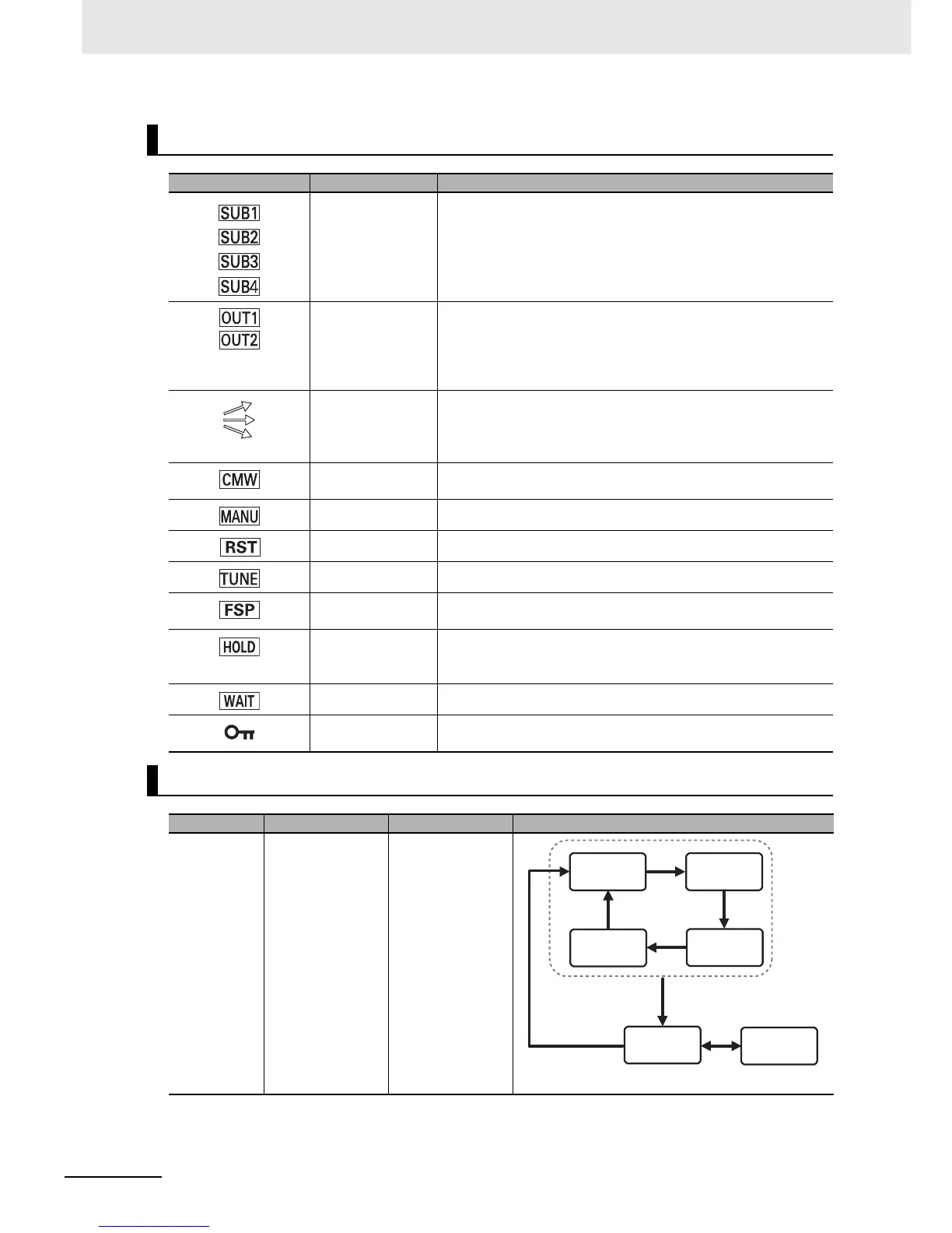
Indicators
Operation indicators Name Description
Auxiliary outputs 1
to 4 (auxiliary
output 4:
E5EC-T/E5AC-T
only)
Each indicator lights when the function that is assigned to
corresponding auxiliary output (1 to 4) is ON.
Control outputs 1
and 2
Each indicator lights when the function that is assigned to
corresponding control output (1 or 2) is ON. (For a linear current
output, the indicator is not lit only for a 0% output.)
For a Position-proportional Model, OUT1 lights when the open
output is ON and OUT2 lights when the close output is ON.
Program status
indicators
(E5EC-T/E5AC-T
only)
The program status indicators show the direction of change of the
present SP in the present segment. The indicators light as follows:
Rising segment: top indicator, constant-temperature segment:
middle indicator, and falling segment: bottom indicator.
Communications
writing
This indicator lights when wiring with communications is enabled.
Manual This indicator is lit in Manual Mode.
Reset This indicator is lit while the program is being reset
AT in progress This indicator is lit during autotuning.
Fixed SP This indicator is lit when the SP Mode is Fixed SP Mode while
control is in progress.
Hold
(E5EC-T/E5AC-T
only)
This indicator is lit while the program is being held.
Wait Lit while the program is in wait status.
Setting change
protection
This indicator is lit while setting change protection is ON.
Keys
Key Name Overview Description
O
Level Key Selects the setting
level.
The next setting
level depends on
how long the key is
pressed.
Press
O
Key
for less than 1 s.
Press
O
Key
for less than 1 s.
Press
O
Key for at
least 3 s in any
setting level.
Press
O
Key for
at least 1 s.
Operation
Level
Program
Setting Level
Adjustment
Level
PID
Setting Level
Initial Setting
Level
Communications
Setting Level