A Appendices
A - 18
E5@C-T Digital Temperature Controllers User’s Manual (H185)
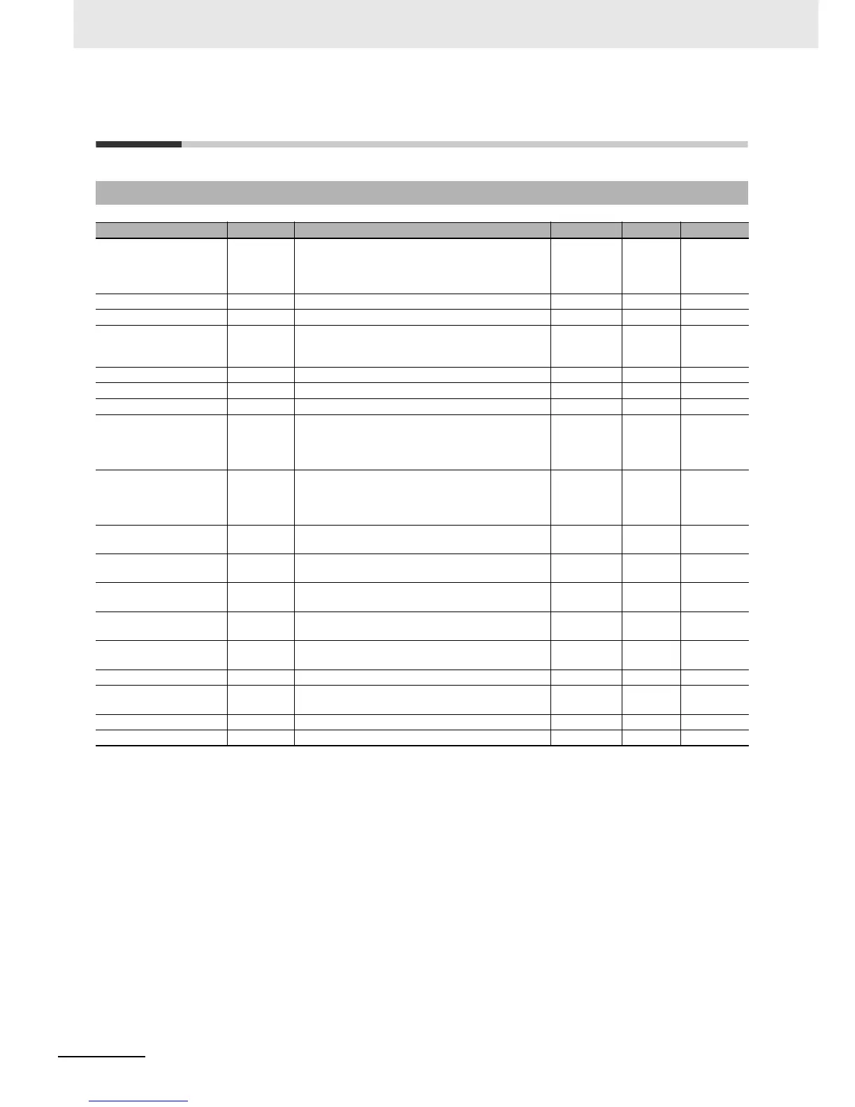
A-6 Parameter Operation Lists
A-6-1 Operation Level
Parameter Characters Setting (monitor) value Display Default Unit
Process Value (1) (2) Temperature: According to indication range for each
sensor.
Analog: Scaling lower limit
−5% FS to Scaling upper limit +5% FS
EU
Set Point (1) (2) SP lower limit to SP upper limit 0 EU
Auto/Manual Switch a-m Auto/Manual Automatic None
Program No. Monitor/
Segment No. Monitor
pgsg During Program Operation
Program number: 0 to 7
Segment number: 0 to 31
0.00 None
Program Number prg 0 to 7 0 None
Hold hold ON or OFF on, off OFF None
Segment Number seg 0 to 31 None
Remaining Standby Time
Monitor
stbm Standby time in hours and minutes: 0.00 to 99.59
Standby time in days and hours: 0.00 to 99.23
Hours and
minutes, or
days and
hours
Elapsed Program Time
Monitor
prgt 0.00 to 99.59 Hours and
minutes, or
minutes and
seconds
Program Execution
Repetitions Monitor
rptm 0 to 9,999 Repetitions
Heater Current 1 Value
Monitor
ct1 0.0 to 55.0 A
Heater Current 2 Value
Monitor
ct2 0.0 to 55.0 A
Leakage Current 1
Monitor
lcr1 0.0 to 55.0 A
Leakage Current 2
Monitor
lcr2 0.0 to 55.0 A
Run/Reset (program) r-r Run or Reset run, rst RST None
MV Monitor (Heating) o −5.0 to 105.5 (standard)
0.0 to 105.0 (heating/cooling)
0.0 %
MV Monitor (Cooling) c-o 0.0 to 105.0 0.0 %
Valve Opening Monitor V-m −10.0 to 110.0 0.0 %