E5jK-T
E5jK-T
16
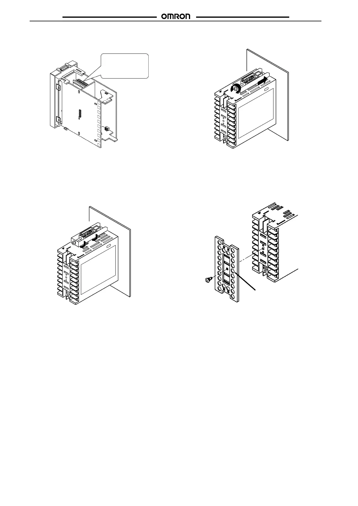
2. Insert the Option Unit into the socket for option 1. The
following diagram shows the relationship between Option
Unit
and mounting position.
Option
1
E53-AKB: Event inputs 1/2
E53-AK01: RS-232C
E53-AK02: RS-422
E53-AK03: RS-485
E53-AKF: T
ransfer output
3. Mount the Option Board and the power board in the order
shown.
Mounting
1. Insert the E5EK-T Controller into the mounting hole in the
panel.
2. Fit the mounting bracket (accessory) into the fixing slots on
the
top and bottom of the rear case.
3. Tighten the mounting bracket screws alternately a little at a
time
until the ratchet starts to slide.
Setting Up the T
erminal Cover
Fasten the T
erminal Covers (E53-COV0809) to protect terminals.
E5AK-VV2-500 Controller is provided with T
erminal Covers.
Use E53-COV09 for terminals 1 to 10, and E53-COV08 for termi-
nals
11 to 33.
Fasten the T
erminal Covers as follows by using the snap pins.
E5AK-T
E53-COV08
T
o remove the Terminal Covers, pull the edges of the snap pins.