Connection connector for F160-VP Connection connector on the Sensor Controller
Pin No.
Signal name
Pin No.
Signal name
CN3 CN1 CN2
B8 STGOUT1 21 - STGOUT1/SHTOUT1
B9 ERROR 19 - ERROR0
B10 GATE - 15 GATE0
B11 COMOUT1 33 - COMOUT
B12 DO1 - 18 DO1
B13 DO3 - 20 DO3
B14 DO5 - 22 DO5
B15 DO7 - 24 DO7
B16 COMOUT2 34 - COMOUT
B17 DO10 - 27 RUN0
B18 DO12 - 29 BUSY0
B19 DO14 - 31 GATE0
B20 COMOUT3 - 33 COMOUT
- 34
Note: COMOUT is unified in 1 system with shorting B11, B16, and B20.
FH-VPX-F210
l
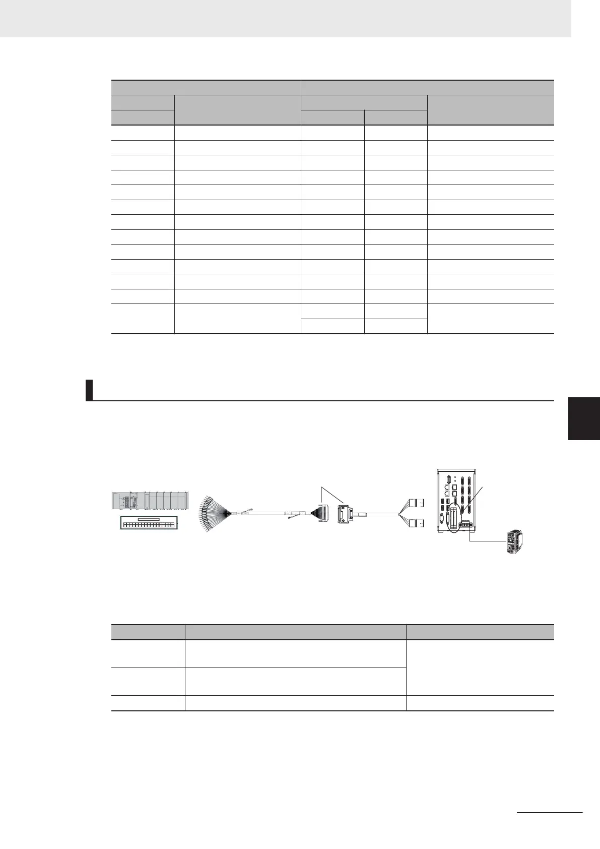
Connection Structure (FH-VPX-F210)
Parallel connector
(CN1/CN2)
FH controller
Connecting the FZ-VP and the FH-VPX-
* After the connection, lock it securely.
PLC, terminal blocks or
other products
Power supply used
in the FH controller:
Power supply S8VS
series (24 VDC)
CN1
CN2
F160-VP
FH-VPX-F210
CN3
Connector No. Connection destination Note
CN1 Connect to the parallel port CN1 on the Sensor Con-
troller
.
Even if you connect the CN1 and
CN2 reversely by mistake, it does
not work but will not be damaged.
CN2 Connect to the parallel port CN2 on the Sensor Con-
troller
.
CN3 Connect to the Parallel I/O cable F160-VP. -
6 I/O Interface
6-27
FH Series Vision System Hardware Setup Manual (Z366-E1)
6-1 Parallel Interface
6
6-1-4 Other (Parallel Converter Cable)
 Loading...


