26
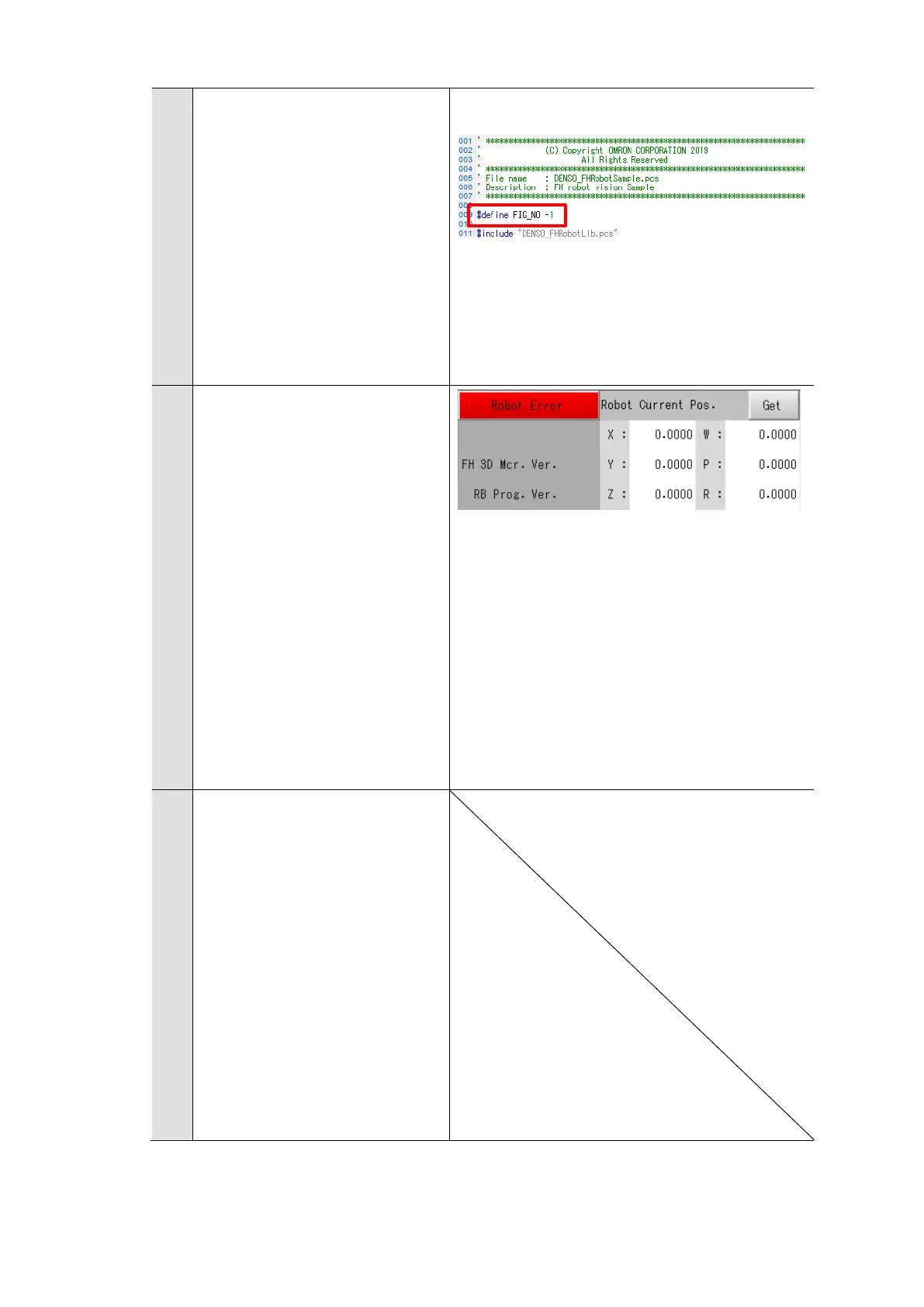
* For the program default,
the DENSO Robot motion
figure (Fig) is used.
Motion figure (Fig): -1
If needed, change the
”#define FIG_NO -1” header
in
DENSO_FHRobotSample.pcs.
5
(Operation of the Teaching
pendant and the Vision
Sensor)
As shown on the right, when
“Robot Error” is show on the
Main Window of the Vision
Sensor, connection was failed.
On the basic screen of the
Teaching Pendant, select
[SHIFT] and press the [F5
MessageLog] Button. Check
error message and the
wiring.
6
(Operation of the Teaching
pendant and the Vision
Sensor)
The connection between the
Vision Sensor and the robot
controller was completed
successfully.
On the basic screen of the
Teaching Pendant, press the
[Reset] Button to reset the
program.

 Loading...


